Method of removing boiler tubes

a technology of boiler tubes and cylinders, which is applied in the field of removing tubes, can solve the problems of affecting the operation of the boiler, and affecting the operation of the boiler, and achieves the effects of reducing the cost of special-purpose cutting tools, and reducing the cost of boiler repair

Inactive Publication Date: 2006-08-22
CRAIG MERRILL C
View PDF7 Cites 26 Cited by
  • Summary
  • Abstract
  • Description
  • Claims
  • Application Information

AI Technical Summary

Benefits of technology

[0005]The present invention provides a new and improved method for removing boiler tubes from a boiler vessel without damaging the vessel. In practicing the invention, the boiler tube to be removed is severed near the exterior periphery of the boiler vessel, and a piloted rotary cutting tool fixtured with respect to the longitudinal axis of the severed boiler tube is used to remove all but a very thin shell of the severed tube. Preferably, the remaining shell has a thickness in the range of 0.015 inch to 0.030 inch. The rotary cutting tool is then withdrawn, and the remaining thin shell of the boiler tub

Problems solved by technology

This typically damages the boiler vessel openings, which must then be repaired before installation of replacement boiler tubes.
While this technique adequately addresses the problem

Method used


Image

  • Method of removing boiler tubes
  • Method of removing boiler tubes
  • Method of removing boiler tubes

Examples


Embodiment Construction

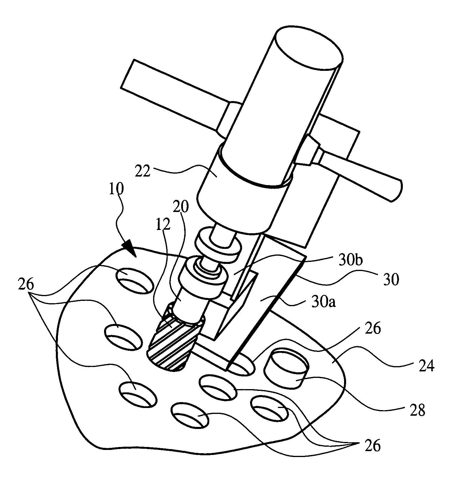
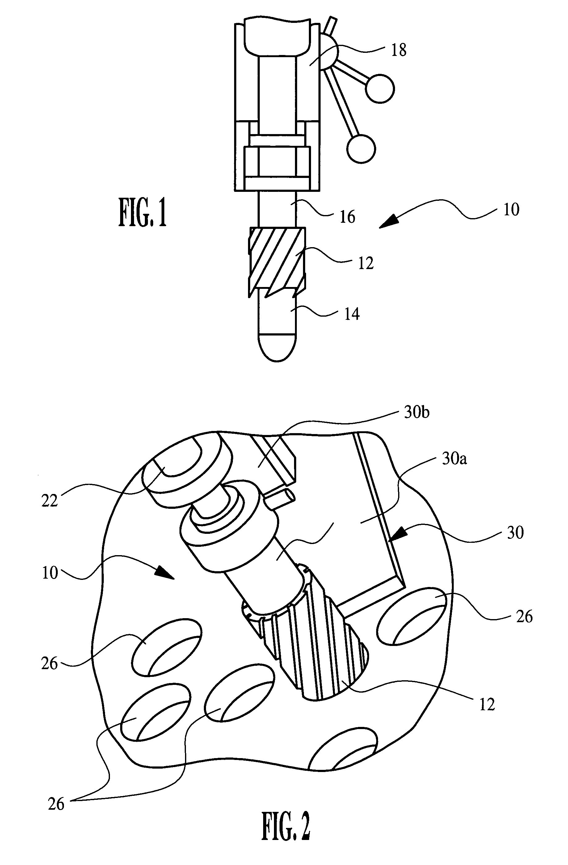
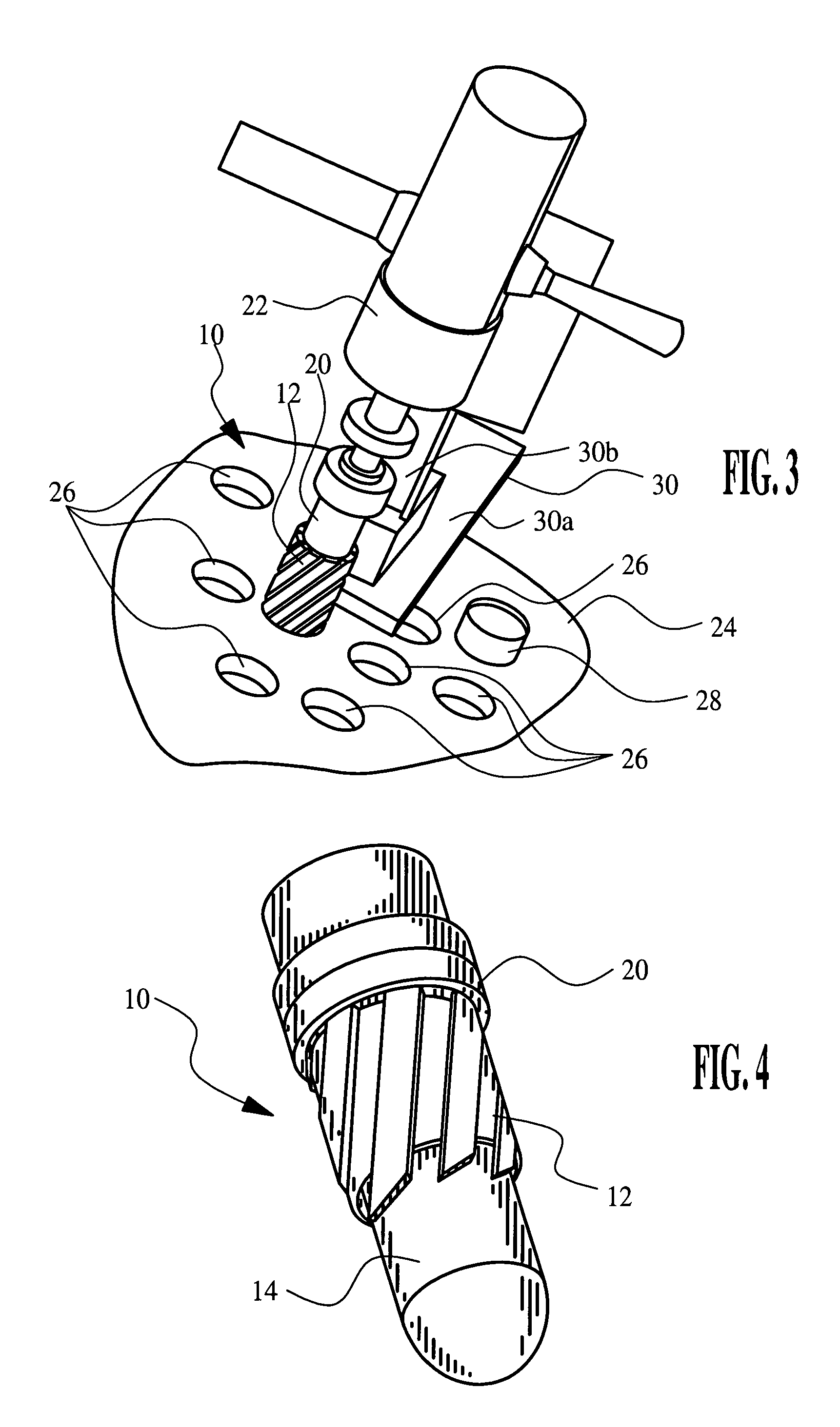
[0010]Referring to the drawings, the reference numeral 10 generally designates a piloted annular rotary cutting tool, including an annular rotary cutting tool 12 and a cylindrical bullet-nosed pilot 14 that is partially received within the annulus of the rotary cutting tool 12. The cutting tool 12 has a cutting diameter that is 0.015 inch to 0.030 inch smaller than the diameter of a boiler tube opening, and the pilot 14 has a primary outside diameter that is slightly smaller than the inside diameter of the expanded portion of the boiler tube. The rotary cutting tool 12 may be an industrial rotary cutting tool, such as manufactured and marketed by Hougen Manufacturing, Inc, in Swartz Creek, Mich., and has a shank extending from its base for securing the cutting tool 12 in a rotary drill.

[0011]In a preferred embodiment, the pilot 14 is retractably mounted within the cutting tool 12 so that it will retract into the body of the cutting tool 12 as it contacts an un-expanded portion of th...


PUM

PropertyMeasurementUnit
Thicknessaaaaaaaaaa
Thicknessaaaaaaaaaa
Diameteraaaaaaaaaa

Abstract

Boiler tubes are removed from a boiler vessel without damaging the vessel by severing the boiler tube near the exterior periphery of the vessel, and using a piloted rotary cutting tool fixtured with respect to the longitudinal axis of the severed boiler tube to remove all but a very thin shell of the severed tube. The rotary cutting tool is then withdrawn, and the remaining thin shell of the boiler tube is manually peeled away from the periphery of the boiler vessel opening. In a preferred implementation, the rotary cutting tool is annular, and a tapered cylindrical pilot having an outside diameter slightly smaller than the inside diameter of the expanded portion of the boiler tube is retractably mounted within the annulus of the cutting tool.

Description

[0001]This claims benefit of 60 / 559,759 filed Apr. 6, 2004.TECHNICAL FIELD[0002]The present invention relates to removing tubes from a fire tube or water tube boiler in connection with boiler maintenance and repair, and more particularly to a method by which the tubes may be quickly and easily removed without damaging the boiler drum.BACKGROUND OF THE INVENTION[0003]Fire tube and water tube boilers designed for commercial and industrial applications have two or more heavy duty drums or headers (collectively referred to herein as vessels) interconnected with numerous steel boiler tubes in the range of 2–3 inches in diameter. The boiler tubes are inserted through openings in the boiler vessel, welded to the exterior periphery of the vessel, expanded against the circumference of the openings, and flared or beaded against the vessel on the inner periphery of the openings. Over the life of the boiler, the boiler tubes may be removed and replaced up to five or six times incident to either...

Claims


Application Information

Patent Timeline
IPC IPC(8): B23P6/00
CPCB23B5/163B23B41/10B23B51/0426F22B37/58B23B5/168Y10T408/557B23B2251/60Y10T29/49821Y10T29/49824Y10T29/53122Y10T408/558Y10T29/53117Y10T408/03Y10T29/49734Y10T29/49352Y10T408/5583Y10T408/5584Y10T29/4973Y10T408/8923Y10T29/53113
Inventor CRAIG, MERRILL C.
Owner CRAIG MERRILL C
Why Eureka
Try Eureka