Extended operability aircraft fuel delivery system

a technology of aircraft turbine engine and fuel delivery system, which is applied in the direction of hot gas positive displacement engine plants, machines/engines, climate sustainability, etc., can solve the problems of increasing the net positive suction pressure required at the main pump inlet, dissolved gases within the liquid fuel increase and reduce the amount of dissolved gases , the effect of increasing the range of operation of the fuel system

Inactive Publication Date: 2006-08-22
RTX CORP
View PDF13 Cites 36 Cited by
  • Summary
  • Abstract
  • Description
  • Claims
  • Application Information

AI Technical Summary

Benefits of technology

[0008]The fuel within the fuel tank absorbs gases through its contact with air. Dissolved gases release and form a fuel vapor that flows along with the liquid portion of the fuel. A fuel de-aerator is disposed between the tank boost pump and the main pump inlet for removing dissolved gases from the fuel. The fuel de-aerator includes a permeable membrane in contact with the fuel flow. The permeable membrane is supported on a porous backing. A partial pressure differential across the permeable membrane is created to draw dissolved gases from the fuel across the permeable membrane and away from the fuel flow. The gases removed from the fuel are then exhausted from the fuel delivery system. The resulting fuel that is pumped to the main pump inlet includes a substantially reduced amount of dissolved gases. The reduction in dissolved gases increases the range of operation of the fuel system by decreasing the required net positive suction pressure at the main pump inlet.
[0009]Accordingly, the fuel system of this invention includes a fuel de-aerator for removing gases from the fuel to eliminate vapor formation and decrease the required net positive suction pressure to provide an increased range of fuel flow rates.

Problems solved by technology

The fuel system for the turbine engine is limited by the range of fuel flow rates that are capable of supplying a net positive suction pressure required in the centrifugal stage of the main fuel pump.
Cavitation in the pump is not desirable because the collapsing vapor bubbles can cause excessive noise and vibration at the main fuel pump.
Disadvantageously, dissolved gases within the liquid fuel increase the net positive suction pressure required at the main pump inlet.

Method used


Image

  • Extended operability aircraft fuel delivery system
  • Extended operability aircraft fuel delivery system
  • Extended operability aircraft fuel delivery system

Examples


Embodiment Construction

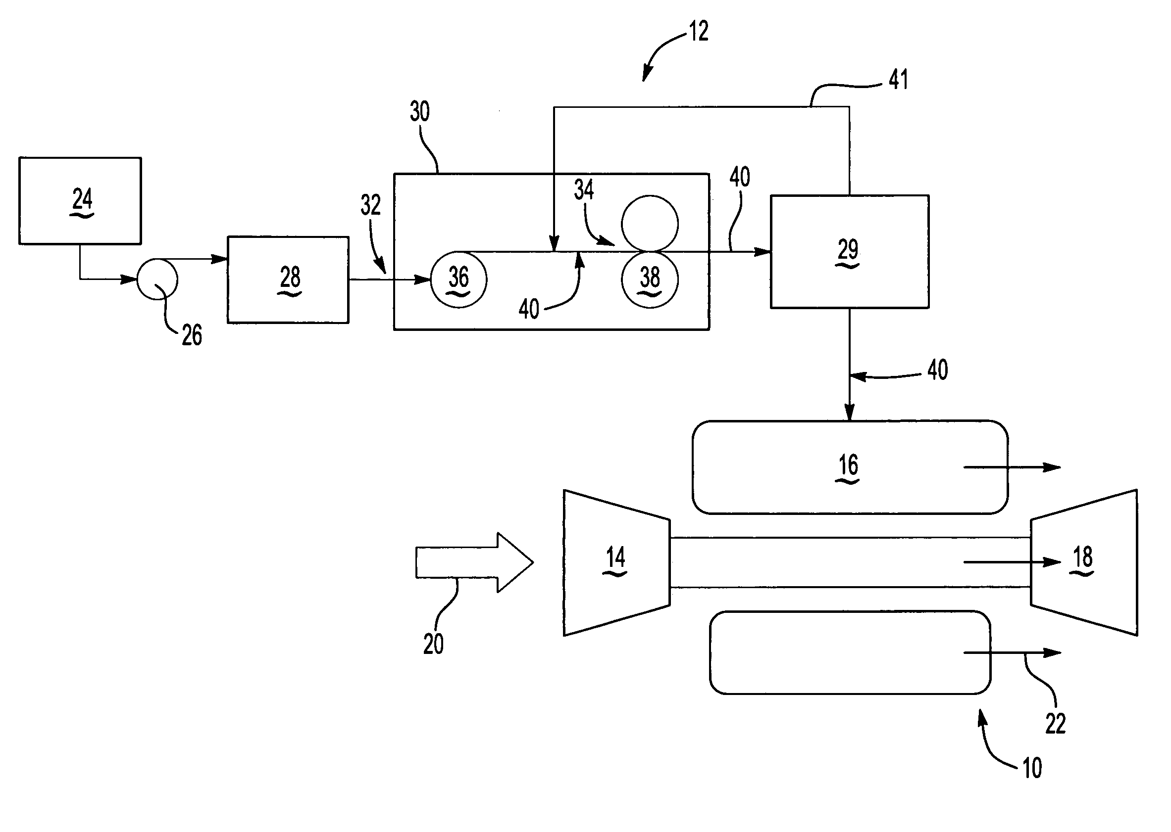
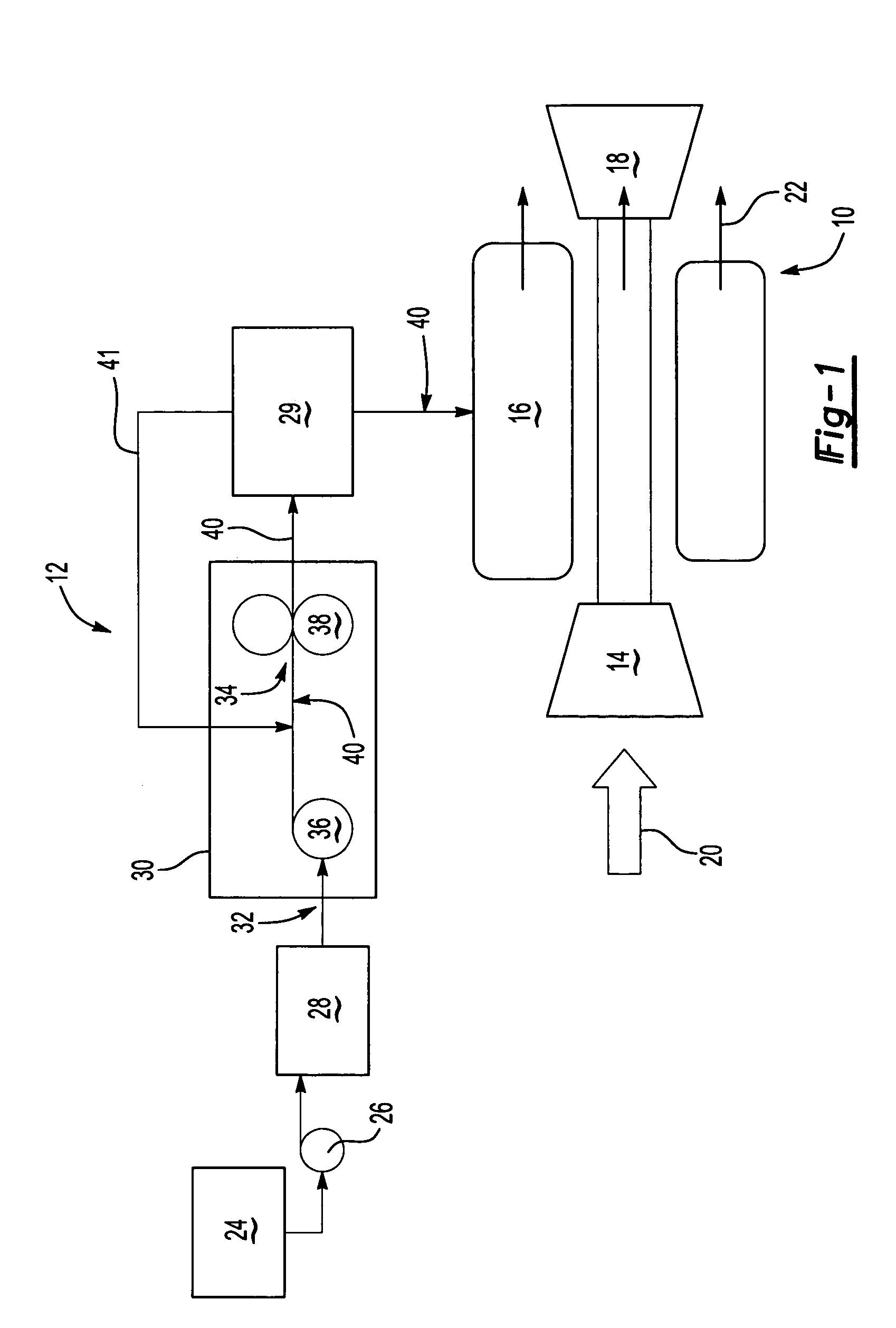
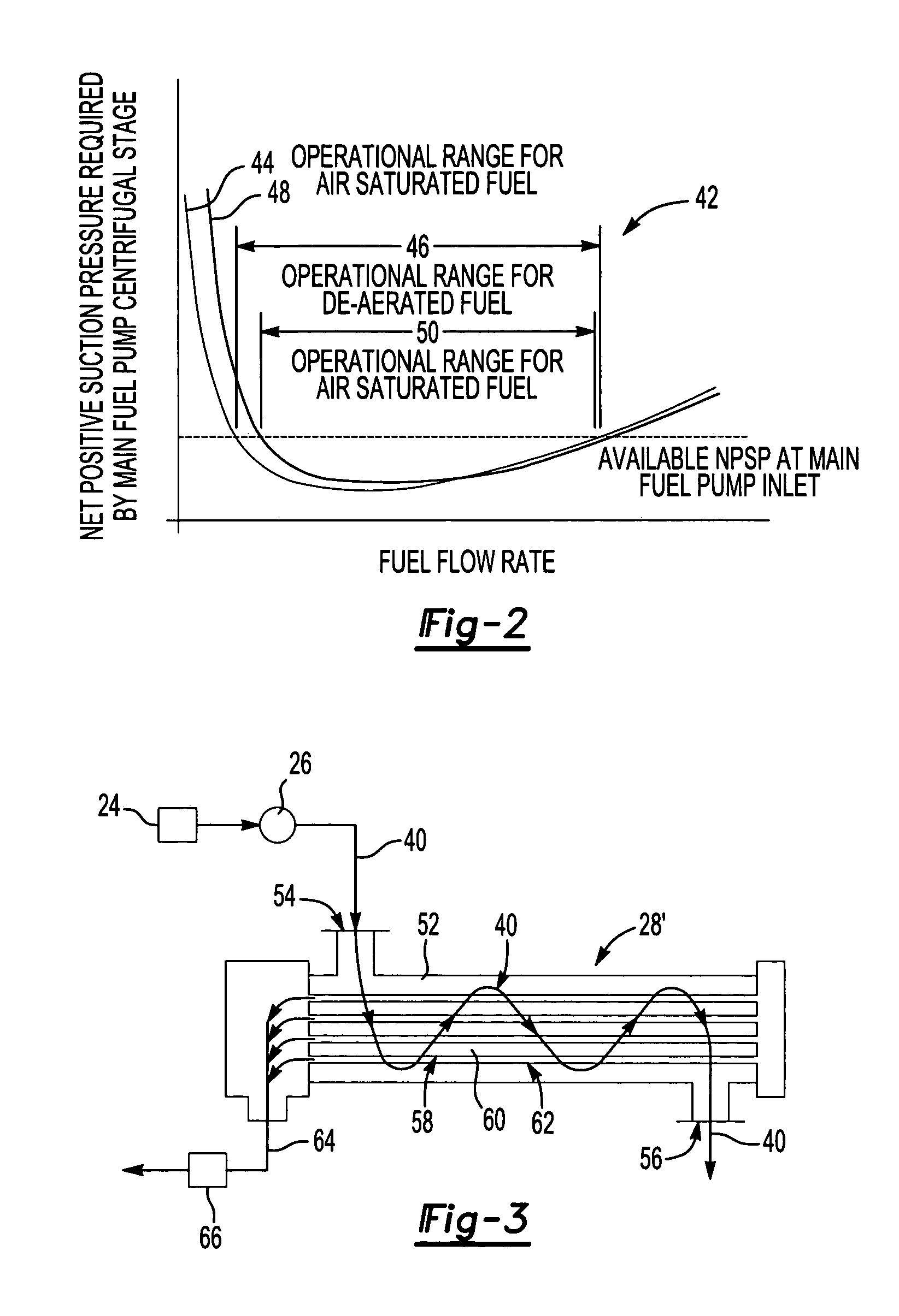
[0016]Referring to FIG. 1, a gas turbine engine assembly 10 is schematically shown and includes a compressor 14, a combustor 16, and a turbine 18. The compressor 14 draws in air 20 and compresses the air to a high pressure. The high-pressure air is mixed with fuel in the combustor 16 and ignited. Hot combustion gases 22 resulting from the ignited fuel drive the turbine 18. A Fuel delivery system 12 supplies fuel 40 to the combustor 16. Removing dissolved gasses within the fuel with a fuel de-aerator 28 optimizes a range of flow rates of fuel from the fuel delivery system 12.

[0017]The fuel delivery system 12 includes a fuel-metering unit 29 that receives fuel from a main pump 30. The main pump 30 includes a centrifugal pump 36 that supplies fuel at pressure to an inlet 34 of a gear pump 38. The gear pump 38 supplies fuel at a constant flow rate to the fuel-metering unit 29. Fuel flow 40 from the gear pump 38 remains constant regardless of system 12 backpressure. Excess fuel flow is r...


PUM


Abstract

A fuel delivery system for a gas turbine engine includes a main fuel pump supplying fuel to a fuel-metering device. The operational flow range of the fuel system is dependent on a minimum net positive suction pressure at the main pump inlet required to prevent pump cavitation. A mixture of fuel and dissolved gases increases the minimum net positive suction pressure required to prevent cavitation. A fuel de-aerator including a permeable membrane removes dissolved gases from the fuel to eliminate formation of dissolved gases. The elimination of dissolved gases from within the liquid fuel reduces the required net positive suction pressure, enabling a greater operational flow range.

Description

BACKGROUND OF THE INVENTION[0001]This invention generally relates to a fuel delivery system for an aircraft turbine engine, and specifically to a fuel delivery system including a fuel de-aerator for removing dissolved gasses within fuel prior to entering a main fuel pump.[0002]A fuel delivery system for a gas turbine engine typically includes a tank boost pump that pumps fuel from a fuel tank to a two-stage main fuel pump. The main fuel pump typically includes a centrifugal stage and a positive displacement stage. In most applications, the main fuel pump and tank boost pump are driven by an engine drive shaft. The main fuel pump centrifugal stage supplies necessary pressure to the inlet of a positive displacement gear stage. Pressure at the inlet of the gear stage is required to fill the cavities of the gear pump with fuel as the gears rotate. Gears rotate at a constant rotational speed to provide a constant flow of fuel to a fuel-metering device. The fuel-metering device receives f...

Claims


Application Information

Patent Timeline
Patent Type & Authority Patents(United States)
IPC IPC(8): F02C7/22B64D37/00B01D19/00B01D61/00F02C7/232F02C7/236F02M37/20
CPCB01D19/0031F02C7/236F05D2270/301F05D2260/96Y02T50/672F23K2900/05082Y02T50/60F02C7/22
Inventor SPADACCINI, LOUIS J.KASLUSKY, SCOTTMCLAUGHLIN, ROBERT A.
Owner RTX CORP
Why Eureka
Try Eureka