Methods and apparatus for mounting a gas turbine engine

a gas turbine engine and mounting lug technology, applied in the direction of couplings, machines/engines, efficient propulsion technologies, etc., can solve the problems of increasing the overall weight of the engine, reducing the overall efficiency of the engine, and causing substantial rotary unbalance load within the damaged fan

Active Publication Date: 2006-08-22
GENERAL ELECTRIC CO
View PDF16 Cites 34 Cited by
  • Summary
  • Abstract
  • Description
  • Claims
  • Application Information

AI Technical Summary

Problems solved by technology

Consequently, a substantial rotary unbalance load may be created within the damaged fan and carried substantially by the fan shaft bearings, the fan bearing supports, and the connector assemblies.
However, increasing the strength of such connector assemblies may undesirably increase an overall weight of the engine and / or decrease an overall efficiency of the engine when the engine is operated without substantial rotor imbalances.

Method used


Image

  • Methods and apparatus for mounting a gas turbine engine
  • Methods and apparatus for mounting a gas turbine engine
  • Methods and apparatus for mounting a gas turbine engine

Examples


Embodiment Construction

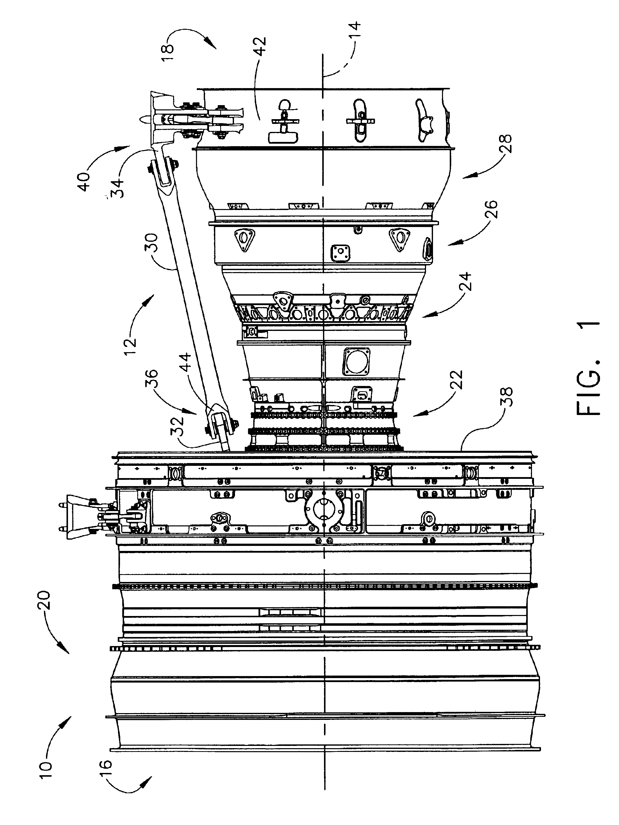
[0016]FIG. 1 is a perspective view of an exemplary gas turbine engine 10 including a known connector assembly 12. Engine 10 has a longitudinal or axial centerline axis 14 extending from an inlet end 16 to an exhaust end 18. Engine 10 includes a fan assembly 20, a high pressure compressor 22, and a combustor 24. Engine 10 also includes a high pressure turbine 26, and a low pressure turbine 28.

[0017]Connector assembly 12 includes a thrust link 30 and a pair of mounting lugs or yokes 32 and 34. An upstream end 36 of thrust link 30 is coupled to a forward fan frame 38 by mounting lug 32, and a downstream end 40 of thrust link 30 is coupled to an aft turbine frame 42 by mounting lug 34. Each mounting lug 32 and 34 includes a spherical bearing (not shown) that is received within a clevis 44 formed at each thrust link end 36 and 40. More specifically, the spherical bearings enable engine thrust loading to be transmitted from forward fan frame 38 through thrust link 30 to aft turbine frame ...


PUM


Abstract

A method enables a thrust link including a clevis to be coupled to a mounting lug including a spherical bearing. The method comprises positioning the spherical bearing within the thrust link clevis, and coupling the thrust link to the mounting lug by inserting a fastener through the clevis such that the fastener extends from one side of the clevis through the spherical bearing to the other side of the clevis, and such that fuse element included with at least one of the fastener and the clevis is positioned within a structural load path defined between the clevis and the thrust link, wherein the fuse element is configured to fail when subjected to a predetermined load.

Description

BACKGROUND OF THE INVENTION[0001]This application relates generally to coupling assemblies and, more particularly, to methods and apparatus for coupling a thrust link to a mounting lug.[0002]At least some known coupling assemblies include a thrust link that is coupled to a mounting lug or yoke to support a secondary structure. For example, such coupling assemblies may be used to support secondary structures, such as geardrive trains, or turbomachinery. The thrust link provides the loadpath through which engine thrust is transmitted to the aircraft pylon / wing structure. More specifically, the thrust link includes a clevis end that is sized to receive a spherical bearing extending from the mounting lug.[0003]Gas turbine engines typically include a rotor assembly, a compressor, and a turbine. The rotor assembly includes a fan that includes an array of fan blades extending radially outward from a rotor shaft. The rotor shaft transfers power and rotary motion from the turbine to the comp...

Claims


Application Information

Patent Timeline
Patent Type & Authority Patents(United States)
IPC IPC(8): F16D1/12F02C7/20B64D27/26F01D21/04F01D25/28F02C7/32F02K1/80
CPCB64D27/26F01D21/045F01D25/28F02C7/20F02C7/32B64D2027/268Y10T403/32221F05B2240/9151F05B2260/3011Y02T50/671Y10T403/32213Y02T50/60
Inventor WALLACE, THOMAS TRACYGIBBENS, NELSON DIRKPIERCE, MARTIN JOSEPHDYKHUIZEN, CORNELIUS H.
Owner GENERAL ELECTRIC CO
Why Eureka
Try Eureka