

Belt tensioner
a belt tensioner and belt technology, applied in the direction of belts/chains/gears, mechanical instruments, belts, etc., can solve the problems of hard lock mechanism of compression stroke, belt tensioner cannot be used, belt slippage, etc., and achieve the effect of reducing the number of constituting parts and reducing the cos
- Summary
- Abstract
- Description
- Claims
- Application Information
AI Technical Summary
Benefits of technology
Problems solved by technology
Method used
Image

Examples
first embodiment
[0024]FIGS. 1 to 5
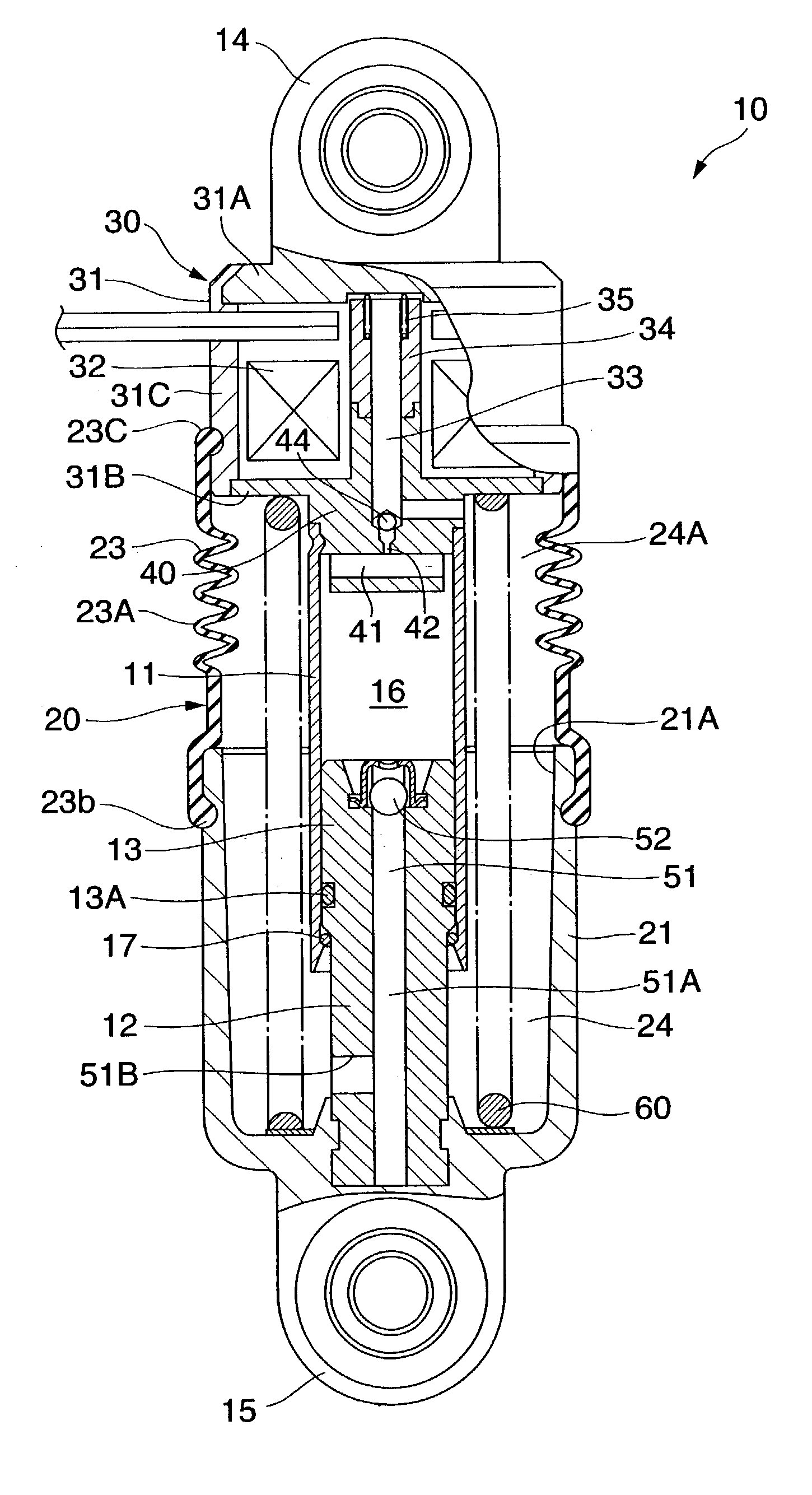
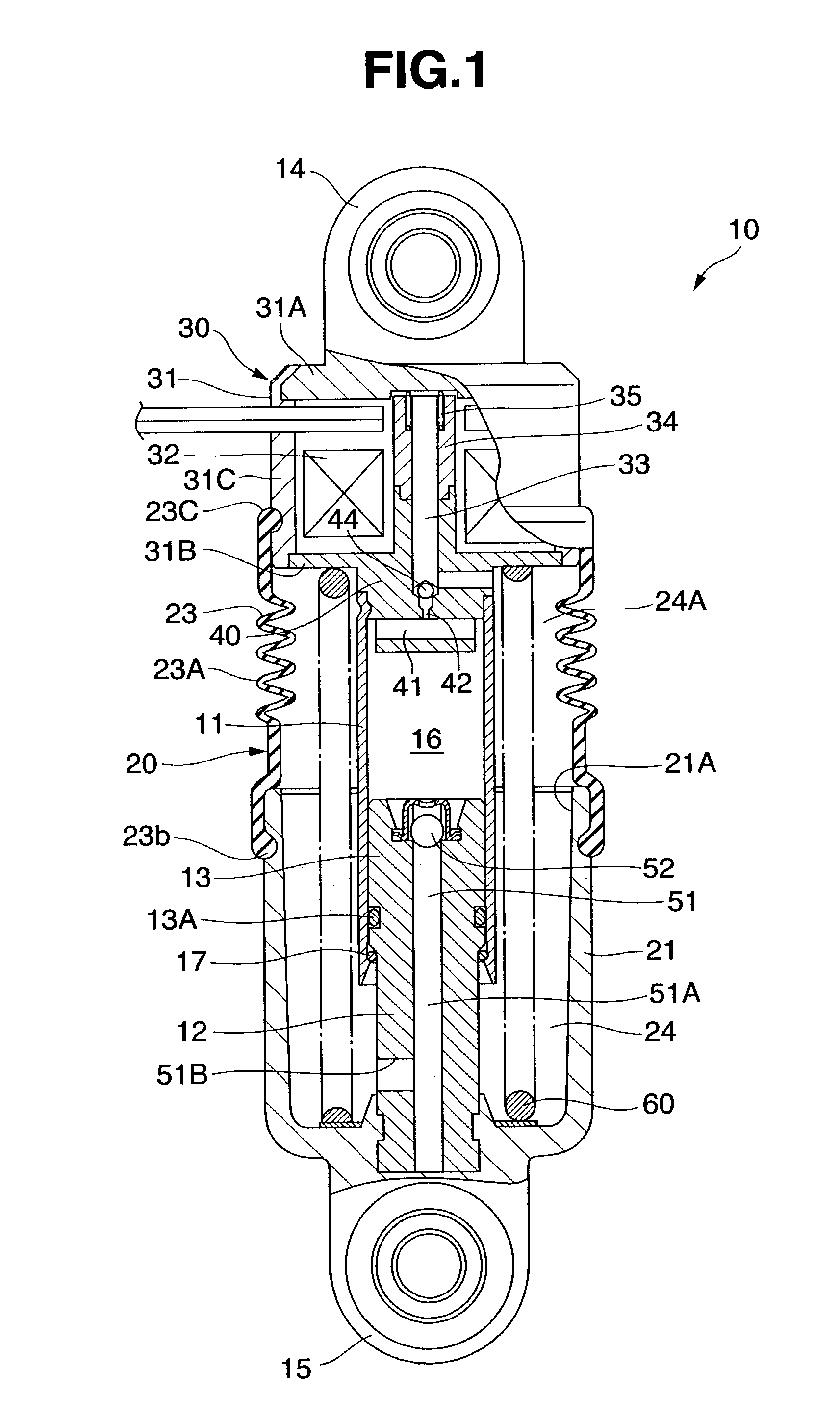
[0025]A hydraulic belt tensioner 10 is provided, for example, between a stationary member such as an engine block or the like and an idle pulley in a hybrid vehicle, and which applies tension to a belt provided in a tensional manner between a drive wheel and a driven wheel by pressing the idle pulley to the belt.
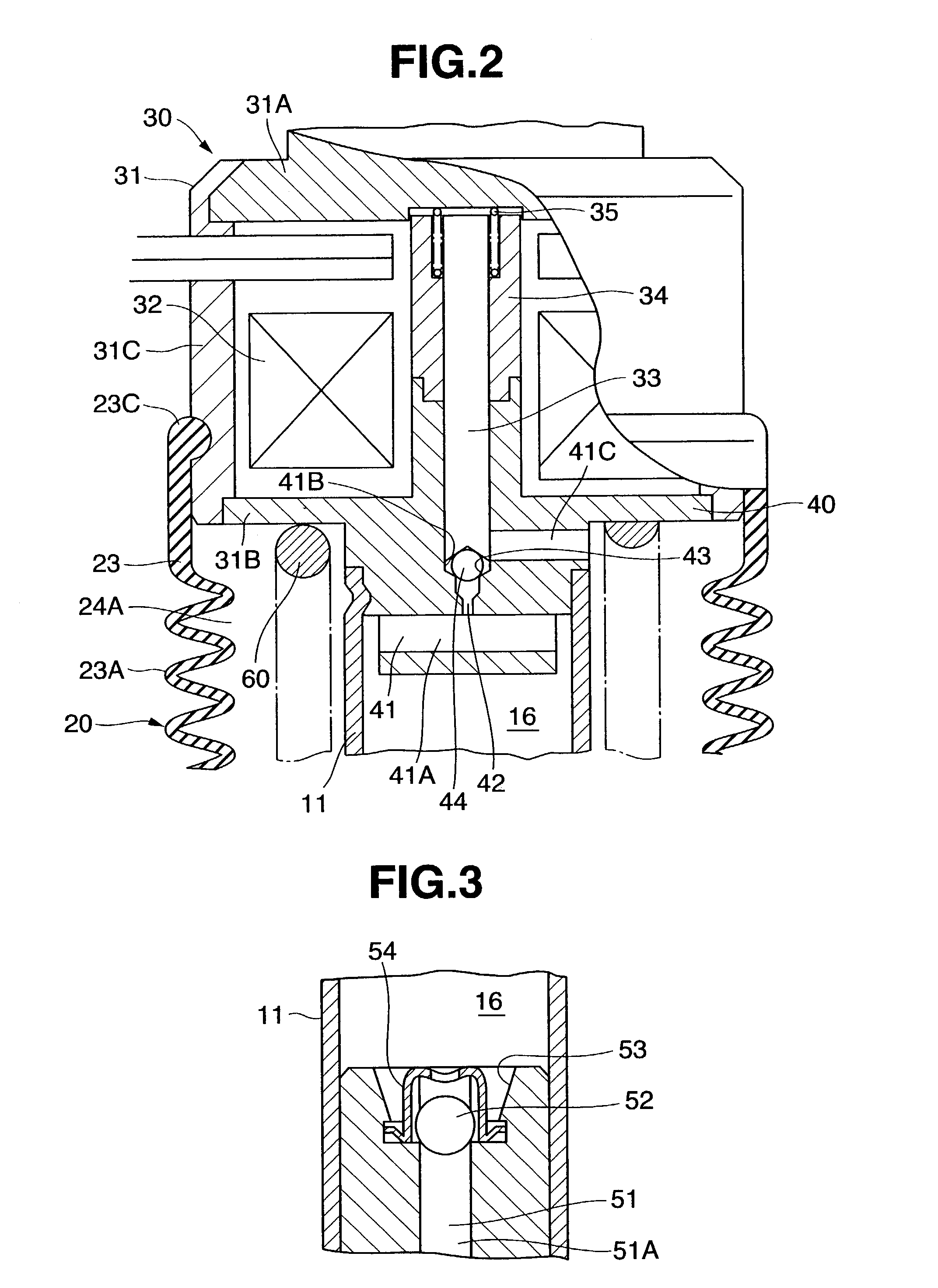
[0026]The belt tensioner 10 is used by slidably inserting a pressurizer 13 provided with a piston ring 13A of a plunger 12 to an inner portion of a cylinder 11, mounting the cylinder 11 to a side of a stationary member positioned in an upper side in a vertical direction, and mounting an idle pulley to a side of the plunger 12, as shown in FIG. 1. The cylinder 11 is fixed to a housing 31 of an electromagnetic valve 30 mentioned below, and is provided with a mounting member 14 in an upper portion of the electromagnetic valve 30. The plunger 12 is provided with a mounting member 15 in a lower portion.
[0027]The belt tensioner 10 forms a high pressure oil chambe...
second embodiment
[0063]The belt tensioner 10 according to the second embodiment is different from the belt tensioner 10 according to the first embodiment in that the casing 21 constituting the outer tube 20 in the first embodiment is replaced by a casing 71 consisting of a press work piece independently provided from the mounting member 15 fixed to the lower portion of the plunger 12. The casing 71 is structured by seating a lower flange portion 72 to the mounting member 15, clamping the flange portion 72 by the spring 60, and fitting an upstanding portion 73 in an inner periphery of the flange portion 72 to an O-ring 74 provided in the mounting member 15 in a liquid tight manner.
[0064]The dust boot 23 provided with the bellows 23A is provided in the side of the cylinder 11. The dust boot 23 is attached in a liquid tight manner to the casing 71, in the same manner as that of the first embodiment.
third embodiment
nd 8
[0065]The belt tensioner 10 according to the third embodiment is different from the belt tensioner 10 according to the second embodiment in that the dust boot 23 constituting the outer tube 20 in the second embodiment is replaced by a cover 81 consisting of a press work piece. The cover 81 is fixed in a liquid tight manner to an O-ring 82 provided in the outer periphery of the housing 31 of the electromagnetic valve 30 in the side of the cylinder 11, and is fixed to the housing 31 by caulking or the like. An oil seal 83 is fitted in a liquid tight manner to an expanded inner peripheral portion provided in a lower end opening of the cover 81, and is fixed by a stop ring 84. An upper end outer peripheral surface of the casing 71 is inserted in a liquid tight manner to the oil seal 83 of the cover 81. The casing 71 is in slidable contact with the oil seal 83 of the cover 81, thereby absorbing the expansion and contraction of the plunger 12.
[0066]Further, in the belt tensioner 10 ac...
PUM
 Abstract
Description
Claims
Application Information