Low noise optical housing

Active Publication Date: 2006-08-22
JPMORGAN CHASE BANK NA
View PDF143 Cites 820 Cited by
  • Summary
  • Abstract
  • Description
  • Claims
  • Application Information

AI Technical Summary

Benefits of technology

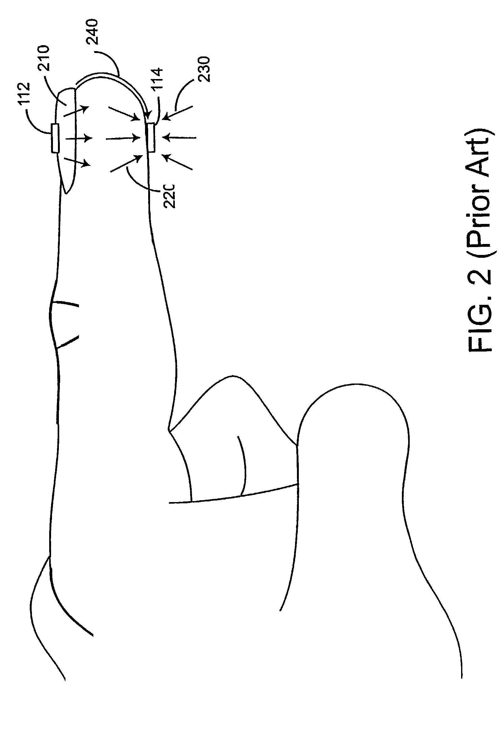
[0003]FIG. 2 illustrates various optical noise sources for a sensor 110 (FIG. 1). Shown is the placement of the sensor LEDs 112 and detector 114 on a finger without showing the associated electrical interconnections, base stock and face stock materials. Emitted light 210 is projected from the LEDs 112 into the fingernail bed. Received light 220 propagates through the finger tissues to the detector 114, subject to absorption and scattering, to generate a desired sensor signal. Light which illuminates the detector 114 without propagating through the finger is unwanted optical “noise” that corrupts the desired sen

Problems solved by technology

Light which illuminates the detector 114 without propagating through the f

Method used


Image

  • Low noise optical housing
  • Low noise optical housing
  • Low noise optical housing

Examples


Embodiment Construction

[0033]FIGS. 4A–C illustrate a low noise optical housing 400 having a protruding cover 410, a generally flat flange 420 disposed around the periphery of the cover 410, and a generally flat base 460 adjoining the flange 420. The housing 400 is configured to accept a detector 820 (FIGS. 6A–B) and provide ambient light and piped light reduction. In particular, the low noise optical housing 400 advantageously incorporates the functions of a light barrier, opaque cover, spacer and aperture, as described with respect to FIG. 3, above, in a relatively small, easy to manufacture, one-piece design.

[0034]As shown in FIGS. 4B–C, the housing 400 is advantageously constructed of a flat substrate which, in one embodiment, is a laminate of two materials including an outer white layer 407 and an inner black layer 408. By utilizing a laminate of both white and black material, the low noise optical housing 400 advantageously functions both as a light absorber and as a light reflector. The white layer ...


PUM


Abstract

Aspects of the invention include an optical housing including a substrate having a reflective side and an absorbing side. The substrate has a generally planar base portion and a protruding cover portion. The cover portion defines a pocket on the absorbing side. The substrate has an open position where the base portion is distal the cover and a closed position where the base portion is proximate the cover. The substrate is configured to enclosed a detector within the pocket in the closed position. The base portion defines an aperture generally centered within the base portion and aligned with the detector in the closed position so as to pass light through to the detector.

Description

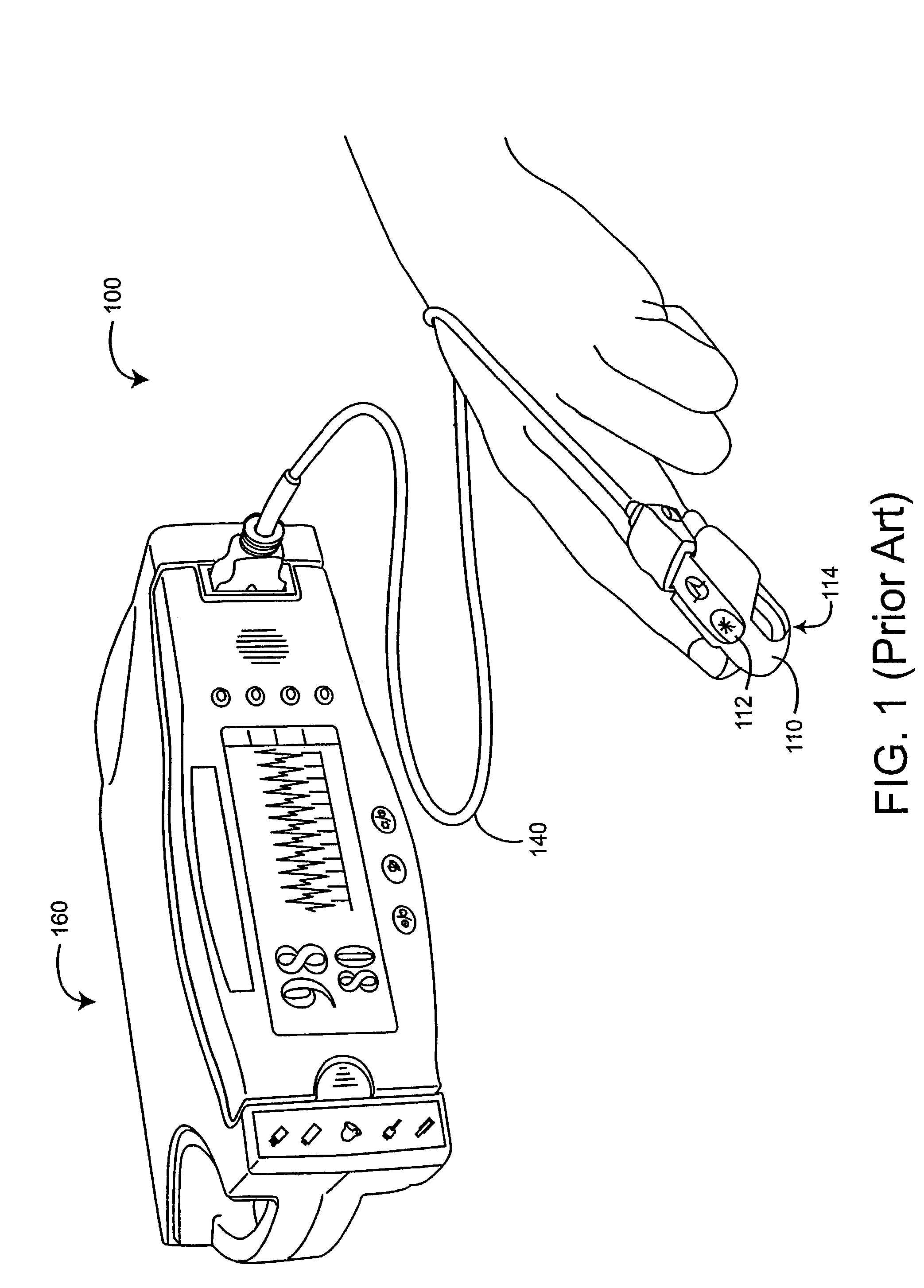
REFERENCE TO RELATED APPLICATION[0001]This application claims the benefit of U.S. Provisional Application No. 60 / 400,177, Aug. 1, 2002. The present application incorporates the foregoing disclosures herein by reference.BACKGROUND OF THE INVENTION[0002]Pulse oximetry is a widely accepted noninvasive procedure for measuring the oxygen saturation level of arterial blood, an indicator of a person's oxygen supply. Early detection of low blood oxygen level is critical in the medical field, for example in critical care and surgical applications, because an insufficient supply of oxygen can result in brain damage and death in a matter of minutes. FIG. 1 illustrates a pulse oximetry system 100 having a sensor 110 applied to a patient, a monitor 160 and a patient cable 140 connecting the sensor 110 and the monitor 160. The sensor 110 is attached to a tissue site, such as an adult patient's finger (as shown). Other sensor types are configured to attach, say, to a neonatal patient's foot. The s...

Claims


Application Information

Patent Timeline
IPC IPC(8): A61B5/00
CPCA61B5/14552A61B2562/182
Inventor ABDUL-HAFIZ, YASSIRSCHMIDT, JOHN
Owner JPMORGAN CHASE BANK NA
Why Eureka
Try Eureka