Multiuse block and retaining wall

a multi-use block and retaining wall technology, applied in the field of retaining wall construction, can solve the problems of inability to achieve setbacks, labor-intensive retaining wall construction, and the requirement that the retaining wall be substantially vertically assembled

Inactive Publication Date: 2006-08-29
MORTARLESS TECH
View PDF32 Cites 41 Cited by
  • Summary
  • Abstract
  • Description
  • Claims
  • Application Information

AI Technical Summary

Benefits of technology

[0017]An advantage of the present invention is that the use of differently sized and oriented preformed blocks permits a retaining wall to be configured into a myriad of configurations.
[0018]Another advantage of the present invention is that each course presents a substantially contiguous, aligned stop surface against which indexing surfaces of projections of an adjacent course of blocks are positioned.
[0019]Additional objects, advantages and features of the invention will be set forth in part in the description which follows, and in part will become apparent to those skilled in the art upon examination of the following or may be learned by practice of the invention. The objects and advantages of the invention may be realized and attained by means of the instrumentalities and combination particularly pointed out in the appended claims.

Problems solved by technology

In the past, retaining wall construction was labor intensive and often required the skills of trained tradespeople such as masons and carpenters.
A drawback with such a retaining wall is that setbacks are not possible and the assembled retaining wall must be substantially vertical.
There are several drawbacks with this type of wall.
One drawback is that the vertical blocks dictate the height of the course.
Another drawback with such this type of wall is that the number of arrangements available within each course is limited, and a truly random arrangement is not possible.

Method used


Image

  • Multiuse block and retaining wall
  • Multiuse block and retaining wall
  • Multiuse block and retaining wall

Examples


Embodiment Construction

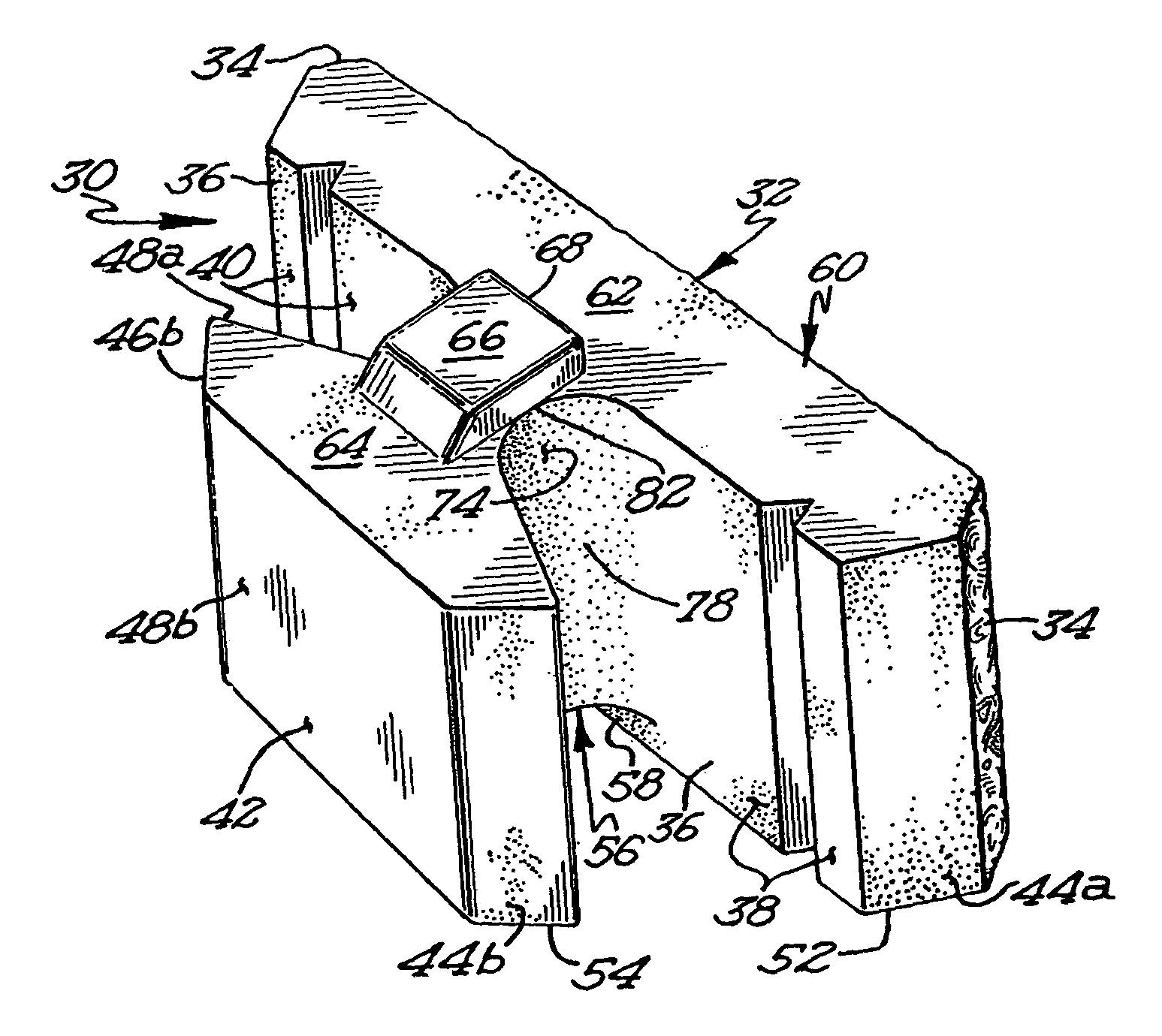
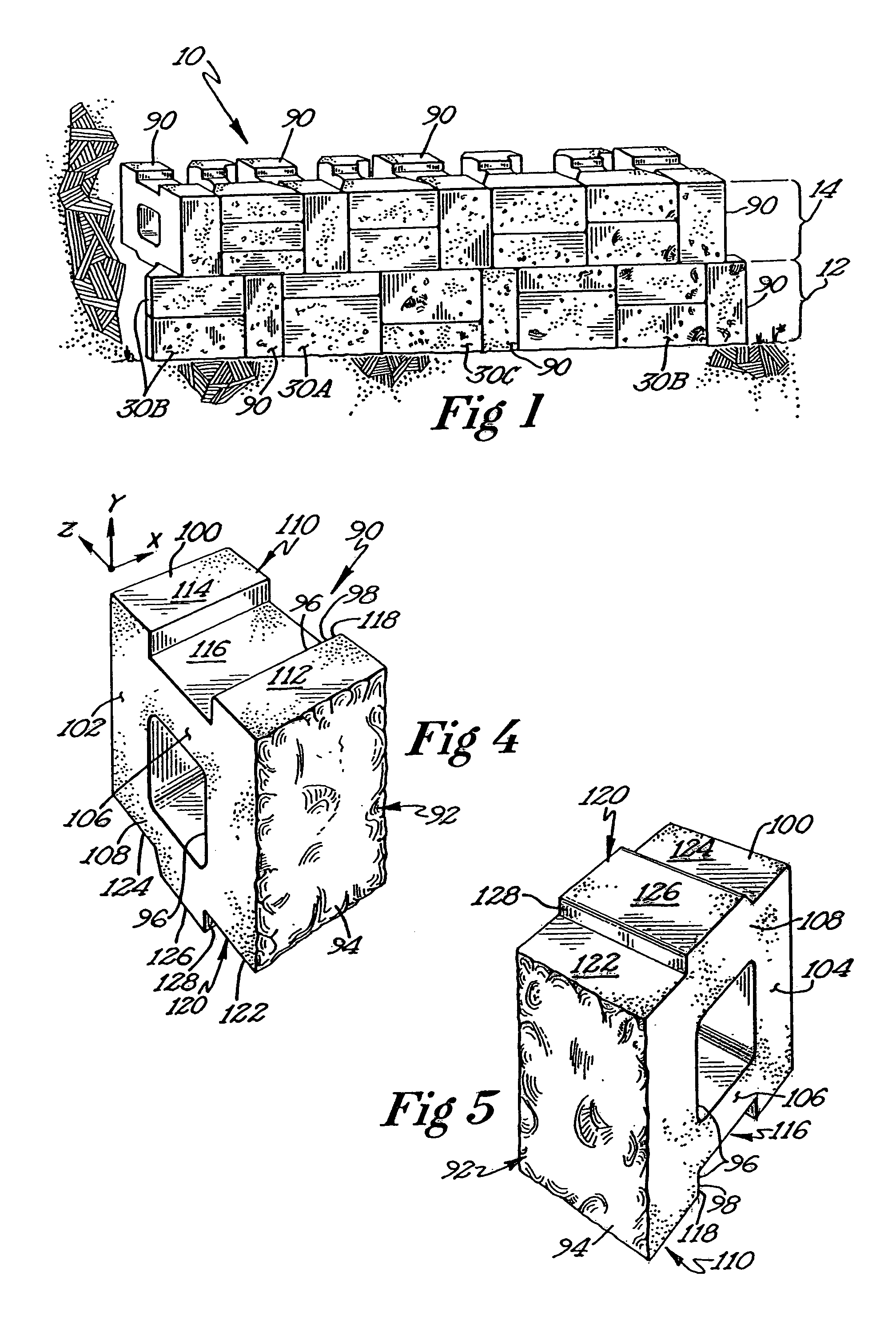
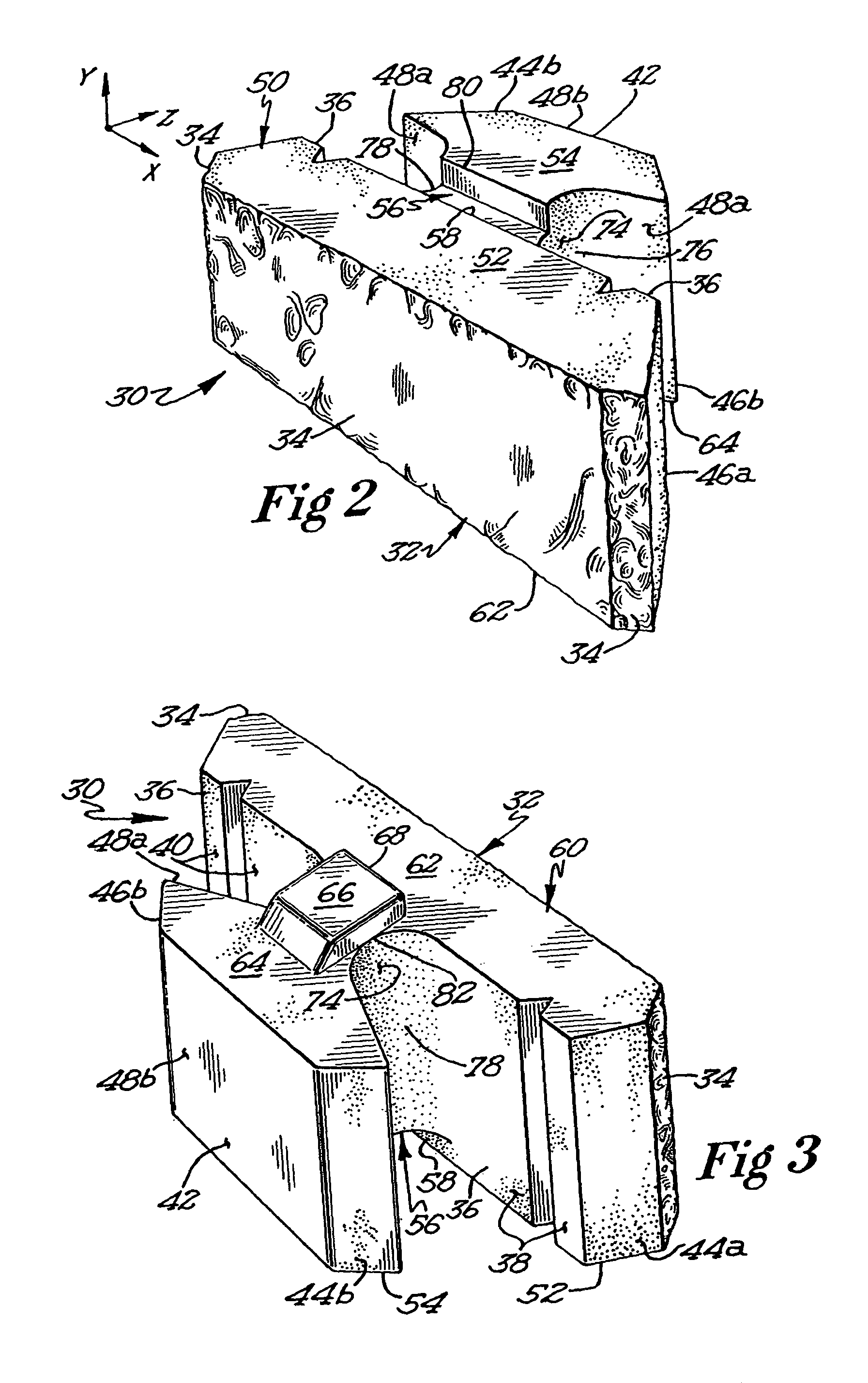
[0033]With reference to the drawings, FIG. 1 shows one embodiment of a retaining wall 10 comprising a plurality of horizontally and vertically oriented preformed blocks 30A, 30B, 30C, and 90 of the present invention. As will be discussed later in greater detail, the horizontal, preformed blocks 30A, 30B, and 30C may be formed in different incremental thickness, and are combinable so that their total thickness is equal to the height of the vertical, preformed blocks 90. As shown in FIG. 1, the horizontal, preformed blocks 30A, 30B, 30C may be selected and stacked in combinations of twos and threes. That is, block 30A and block 30C, two blocks of 30B, and three blocks of 30C. It will be understood, that each course of blocks may be defined by the height of the vertical blocks 90. Thus, beginning with the lower left segment of the wall 10, the first course 12 comprises two stacked 30A blocks, a vertical block 90, two stacked 30A and 30C blocks, two stacked 30C and 30A blocks, a vertica...


PUM


Abstract

A retaining wall with a series of differently sized, pre-formed blocks. Each block includes a projection and a recess, with the projection and recess arranged and configured so that each projection effectively engages a recess in an adjacent course to connect and align adjacent courses in registry. Retaining walls made of horizontal blocks may be stacked in columnar fashion or running bond fashion. The location of the indexing surface on a projection relative to the viewable surface of the block may be varied to enable adjacent courses to be coplanar or tiered in a variety of predetermined offset distances.

Description

CROSS REFERENCE TO PRIOR APPLICATION[0001]This application is a continuation-in-part of prior application Ser. No. 09 / 798,210, filed Mar. 2, 2001, now U.S. Pat. No. 6,651,401 entitled RETAINING WALL AND METHOD OF WALL CONSTRUCTION.FIELD OF THE INVENTION[0002]This invention relates generally to the construction of retaining walls used in landscaping applications where such walls are used to provide lateral support between differing ground levels. More particularly, the present invention relates to a retaining wall that uses a series of differently sized, pre-formed horizontal and vertical blocks that operatively connect with each other along adjacent courses to resist pressure exerted against the wall by retained back-fill material and ground water.BACKGROUND OF THE INVENTION[0003]Retaining walls are widely used in a variety of landscaping applications. Typically, they are used to maximize or create level areas and also to reduce erosion and slumping. They may also be used in a purel...

Claims


Application Information

Patent Timeline
Patent Type & Authority Patents(United States)
IPC IPC(8): E04B5/04E02D29/02E04B2/02E04C1/39
CPCE02D29/025E04C1/395E04B2002/0204E04B2002/0263E04B2002/0269E04B2002/0215
Inventor PRICE, RAYMOND R.PRICE, GERALD P.
Owner MORTARLESS TECH
Why Eureka
Try Eureka