Modular mail preparation system

Inactive Publication Date: 2006-08-29
BELL & HOWELL CO
View PDF11 Cites 31 Cited by
  • Summary
  • Abstract
  • Description
  • Claims
  • Application Information

AI Technical Summary

Benefits of technology

[0008]An objective is to help mail piece processors, such as direct mailers, increase production and reduce labor requirements.
[0009]Another objective is to provide a high-speed, vertical transport sy

Problems solved by technology

Such horizontal-feed address print systems have several limitations.
For example, they are slow: they can process only approximately 18,000–22,000 mail pieces per hour.
In addition, because the mail pieces are fed in a horizontal position, these systems cannot be combined or used with conventional mail processing or sorting systems, which feed and process mail pieces.
If the feed stack is too high, there is too much weight on the bottom mail piece and it will not be

Method used


Image

  • Modular mail preparation system
  • Modular mail preparation system
  • Modular mail preparation system

Examples


Example

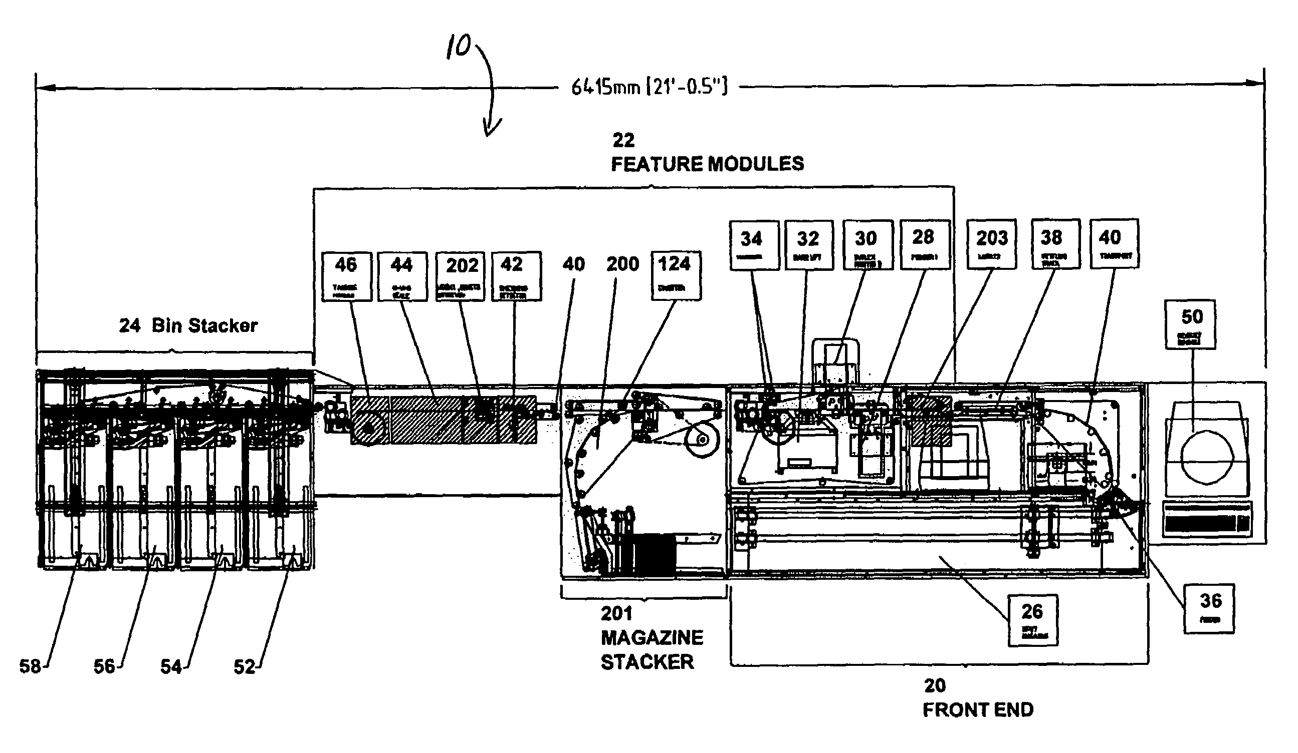
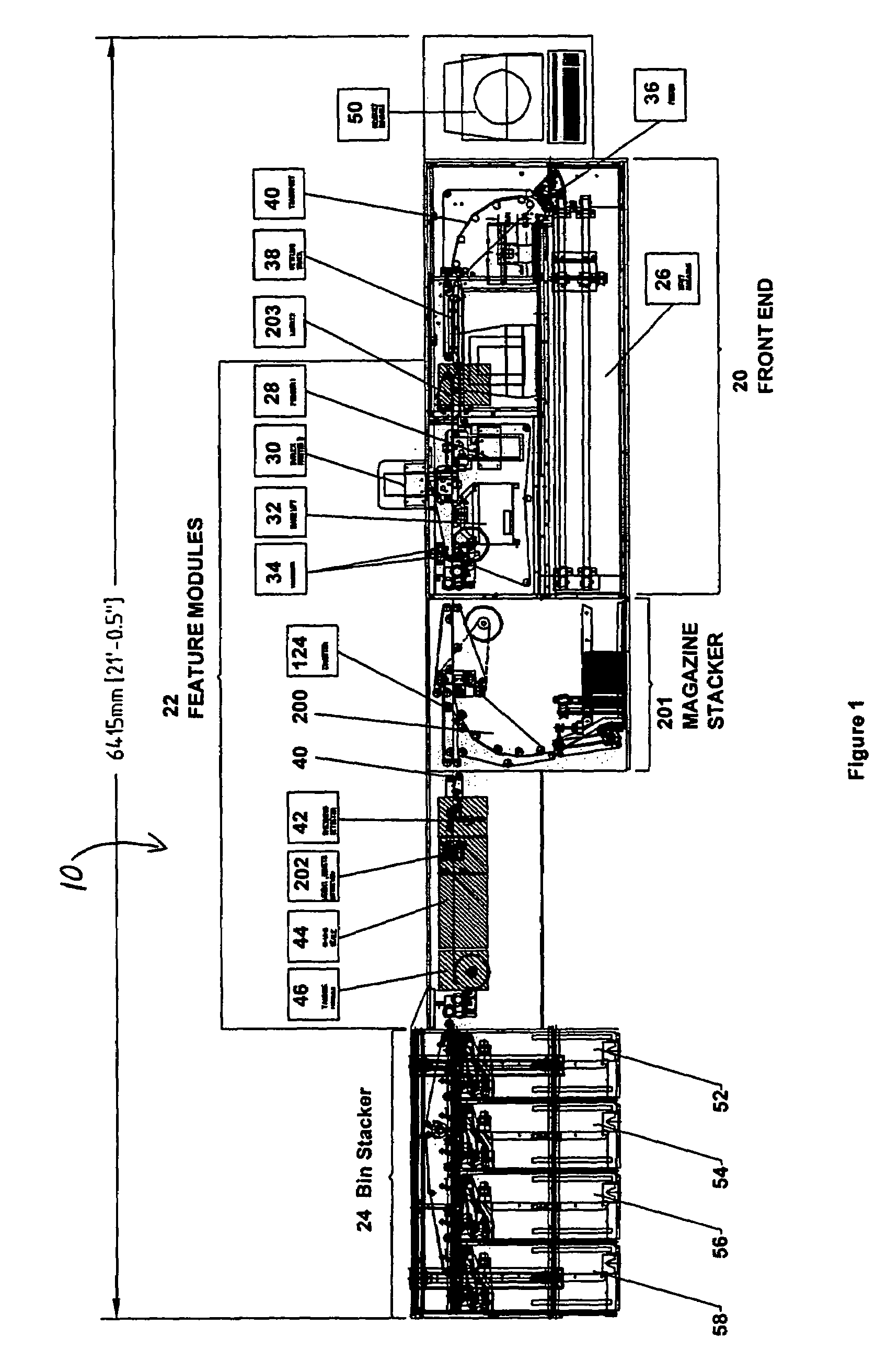
[0023]Referring now to FIG. 1, a modular mail preparation system 10 is shown. As shown, the system 10 has a front end 20, various feature or processing modules (as will be described below) located downstream from the front end 20, and a stacker bin 24 located downstream of the processing modules. In many ways the front end 20 is similar to the front end of an existing mail sorting system such as the Bell+Howell Criterion™ sorting system.

[0024]As shown, front end 20 has an input magazine 26, a feeder 36 and settling track 38. The magazine 26 can hold mail pieces in a vertical or upright position to be fed into and processed by the system 10. As also shown, the magazine section 26 is approximately 75 inches long, however, as will be apparent to one of ordinary skill in the art, the magazine 26, may be longer or shorter. The magazine section 26, like the rest of the system 10, has a series of movable belts, some of which are indicated as reference numeral 40 (See FIGS. 1, 2 and 3), whi...


PUM


Abstract

A mail preparation system for processing a mail piece comprises a magazine section to hold the mail piece and a feeder for feeding the mail piece into a transport path in a vertical position. Mail processing equipment may be placed along the transport path for processing the mail piece.

Description

CROSS-REFERENCE TO RELATED APPLICATION[0001]The present application claims the benefit of U.S. Provisional Application Ser. No. 60 / 542,920 filed Feb. 9, 2004, the disclosure of which is entirely incorporated herein by reference.TECHNICAL FIELD[0002]The present subject matter relates to a mail preparation system for preparing mail pieces. More specifically, the system provides for in-line printing of mail pieces, in-line application of permit indicia marks, as well as verification of print quality, verification to postal requirements and sorting of the mail pieces.BACKGROUND[0003]Current address printing systems are primarily used by direct mail processors (“direct mailers”) to print addresses or other information on mail pieces. Such systems feed mail pieces through the system in a flat or horizontal position, i.e., the front of the envelope is facing upward. In order to print on the mail piece, printers are also placed in a horizontal position, i.e., with the print head facing down...

Claims


Application Information

Patent Timeline
IPC IPC(8): G06F17/00B07C3/00B43M3/04G07B17/00
CPCB07C3/00B43M3/04G07B17/00467G07B2017/00701G07B2017/00483G07B2017/0062G07B2017/00677G07B2017/00241
Inventor CONARD, WALTER S.SCHWABA, DAVIDWOJDYLA, RICHARD
Owner BELL & HOWELL CO
Why Eureka
Try Eureka