Yarn winding machine

a winding machine and winding tube technology, applied in the direction of take-up devices, thin material processing, textiles and paper, etc., can solve the problems of short doffing time, inability to realistically stop the turret for doffing full packages, and inconvenient use of the slip-on device of the tube, etc., to achieve the effect of enlarge the time window

Inactive Publication Date: 2006-08-29
SAURER GMBH & CO KG
View PDF12 Cites 10 Cited by
  • Summary
  • Abstract
  • Description
  • Claims
  • Application Information

AI Technical Summary

Benefits of technology

[0007]The above and other objects and advantages of the invention are achieved by the provision of a winding apparatus of the described type and wherein a movement of the winding spindle in the doffing position has no critical effect on supplying the winding spindle with new tubes. To this end, a guide means for slipping on the tubes is adapted for moving for a short time or distance synchronously with the winding spindle that is moved by the spindle support or turret. This enlarges the time window in which it is possible to slip the tubes on the winding spindle. The guide means follows the winding spindle for a short period, so that it is not necessary to interrupt the rotational movement of the spindle support or turret that is needed for winding the yarns on a second winding spindle located at the winding position.
[0008]A simple positioning occurs in that the guide means is arranged on the side next to the spindle support, that it can be moved between a standby position and an operating position laterally toward the winding spindle, and that in the operating position, the guide means can be mechanically linked with the winding spindle. This enables an easy alignment of the guide means with the winding spindle. Even during the rotational movement of the spindle support, no significant errors occur in the alignment between the free end of the winding spindle and the guide means.
[0009]To enable an axial relative movement between the guide means and the winding spindle also when the guide means and winding spindle are mechanically linked, it is advantageous to provide the guide means with a slide shoe, which lies in the operating position against the winding spindle, and sees to the mechanical linkup. To avoid differences in the sequences of movement, the movement of the winding spindle and the movement of the guide means are advantageously performed during the phase of the mechanical linkup by the drive of the spindle support.

Problems solved by technology

However, such a tube slip-on device is not suitable for winding machines, in which the turret performs a bypassing movement for enabling in the winding position a package buildup on the winding spindle being in this position.
In particular, in the winding process of so-called spin textured yarns, wherein yarns with coarser deniers are produced, and thus entail a rapid package buildup, it is not realistically possible to stop the turret for doffing the full packages or putting on the tubes.
Yet, in the winding of yarns with coarse deniers, only very short doffing times are available.
Any disturbance in such a time-critical tube slip-on process would thus lead to a discontinuation of this process, and a new process would have to be started in a changed position of the winding spindle.

Method used


Image

  • Yarn winding machine
  • Yarn winding machine
  • Yarn winding machine

Examples


Embodiment Construction

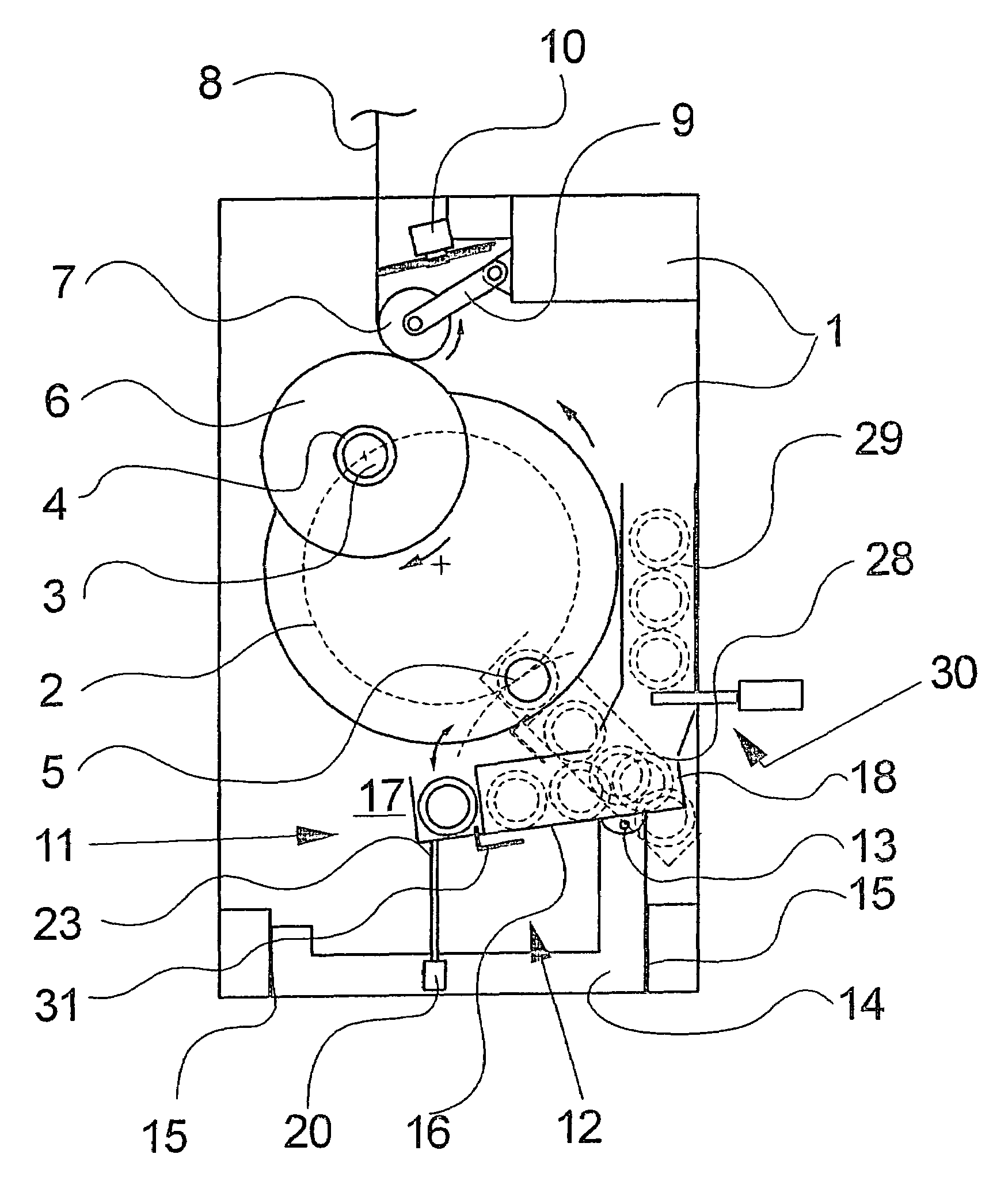
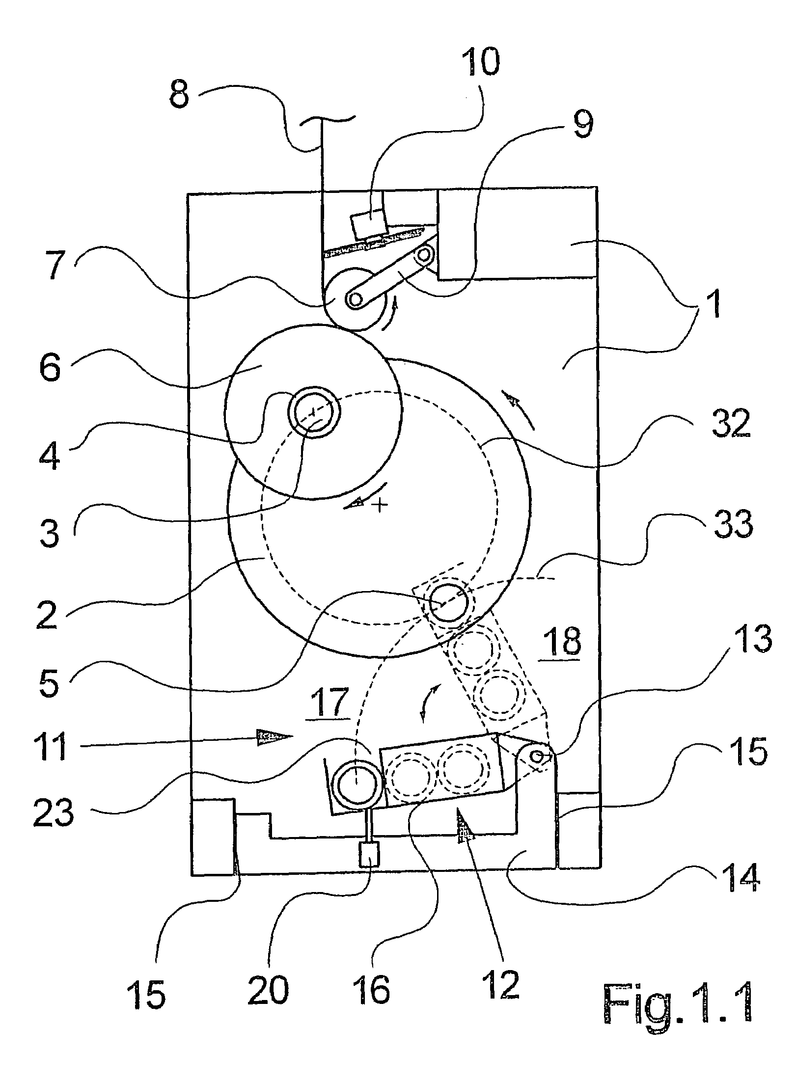
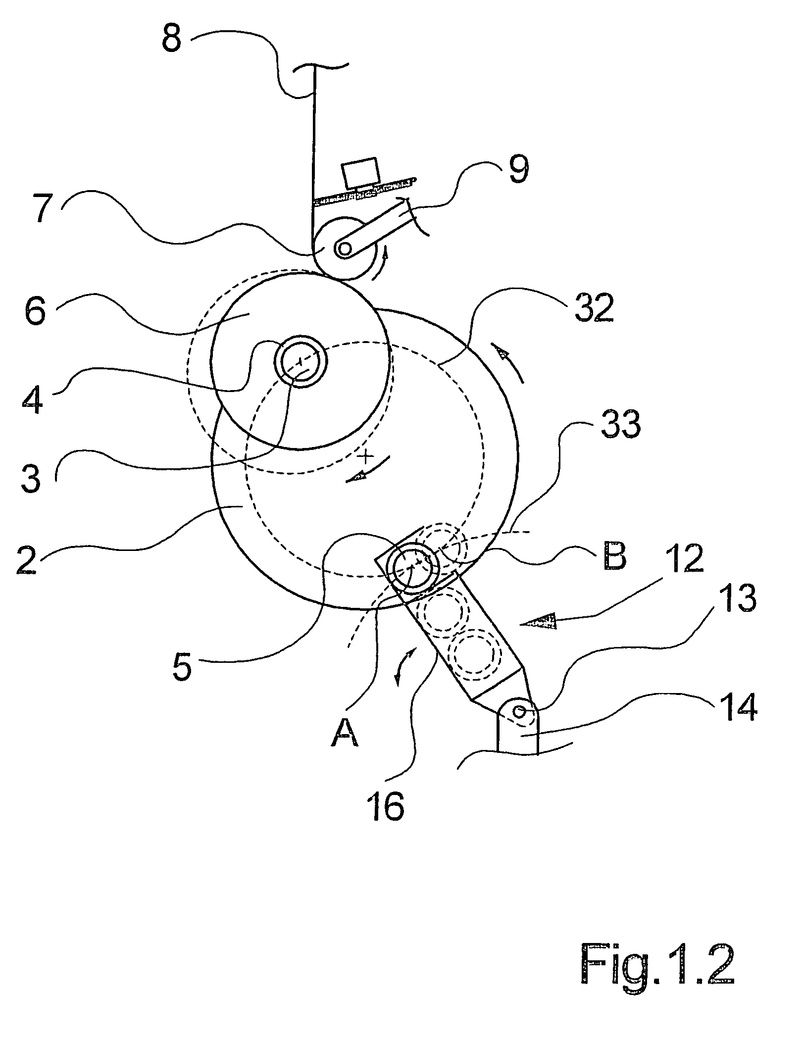
[0025]FIGS. 1.1 and 1.2, and 2.1–2.4 schematically illustrate a first embodiment of the winding machine according to the invention. In this connection, FIGS. 1.1 and 1.2 as well as FIGS. 2.1, 2.2, 2.3, and 2.4 show different operating situations of the winding machine. The following description will apply to all Figures, unless express reference is made to one of the Figures.

[0026]The winding machine comprises a movable spindle support 2, which is rotatably supported in a machine frame 1 so as to define a horizontal central axis. The spindle support 2 is constructed as a turntable or turret and driven anticlockwise by a rotational drive unit 19. The spindle support 2 mounts in cantilever fashion, 180° out of phase, two winding spindles 3 and 5. The winding spindles 3 and 5 are rotatably supported on the spindle support 2 so that their rotational axes are parallel to the central axis. At their supported end, the winding spindles 3 and 5 connect to their respective spindle drive 21 an...


PUM


Abstract

A yarn winding apparatus for continuously winding yarns to packages. The winding apparatus has a plurality of winding spindles, which are mounted in cantilever fashion for rotation on a movable turret, and which are alternately guided between a winding position for winding the yarns and a doffing position for removing the packages and assembling fresh tubes. To put on the tubes on the winding spindle, a tube slip-on device is provided, which comprises a movable means for guiding the tubes. To make it possible to put on tubes on the winding spindles held in the doffing position even during the progressive movement of the turret, the guide means for slipping on the tubes is movable for a short time or distance synchronously with the winding spindle that is moved by rotation of the turret.

Description

BACKGROUND OF THE INVENTION[0001]The present invention relates to a yarn winding machine for continuously winding advancing yarns into packages.[0002]In the production of melt spun yarns in a spinning process, the yarns are wound to packages at the end of the production process. To this end, winding machines are used, which continuously wind a yarn to packages without interrupting the process. To this end, winding machines of this type comprise a plurality of winding spindles, which are mounted on a movable spindle support, also referred to as a turret herein, and alternately moved by means of the turret to a winding position for winding the yarns, and then to a doffing position for removing the fully wound packages and putting on new tubes. The yarn change from a first winding spindle to a second winding spindle occurs automatically, so that the spinning process need not be interrupted.[0003]To slip one or more tubes over the winding spindle held in the doffing position after remov...

Claims


Application Information

Patent Timeline
Patent Type & Authority Patents(United States)
IPC IPC(8): B65H67/048B65H67/04
CPCB65H67/0417B65H2701/31
Inventor MATTHIES, CLAUS
Owner SAURER GMBH & CO KG
Why Eureka
Try Eureka