Installation equipment for display main body and jig for installation equipment

a technology of installation equipment and equipment, which is applied in the direction of television systems, identification means, instruments, etc., can solve the problems of inconvenient adjustment of the tilt of the object, inconvenient installation equipment, complicated installation equipment, etc., and achieve the effect of convenient mounting and simple structur

Inactive Publication Date: 2006-08-29
SAMSUNG ELECTRONICS CO LTD
View PDF14 Cites 44 Cited by
  • Summary
  • Abstract
  • Description
  • Claims
  • Application Information

AI Technical Summary

Benefits of technology

[0010]Accordingly, it is an aspect of the present invention to provide installation equipment for a display main body and a jig for the installation equipment, wherein the installation equipment and the jig have a simple structure and are convenient for mounting the display main body onto a wall.
[0011]Another aspect of the present invention is to provide installation equipment for a display main body and a jig for the installation equipment, which allow the display main body to be tilted easily and finely adjusted, and which are compatible with various sizes of the display main body.

Problems solved by technology

However, the conventional installation equipment is not only complicated because the damping part has the gas damper 160 and wire 161, the locking member 116, etc., but such installation equipment is also inconvenient because, when the user tilts the object, the object can be pushed and pulled when the locking member 116 is released.
Further, in the conventional installation equipment, it is impossible to adjust the tilt of the object finely because the locking member can stepwise lock the tilt of the object.
Furthermore, the conventional installation equipment is not compatible with display main bodies of various sizes because the sizes of the arms and the base depend on the size of the display main body.

Method used


Image

  • Installation equipment for display main body and jig for installation equipment
  • Installation equipment for display main body and jig for installation equipment
  • Installation equipment for display main body and jig for installation equipment

Examples


Embodiment Construction

[0044]Reference will now be made in detail to the embodiments of the present invention, examples of which are illustrated in the accompanying drawings, wherein like reference numerals refer to like elements throughout. The embodiments are described below in order to explain the present invention by referring to the figures.

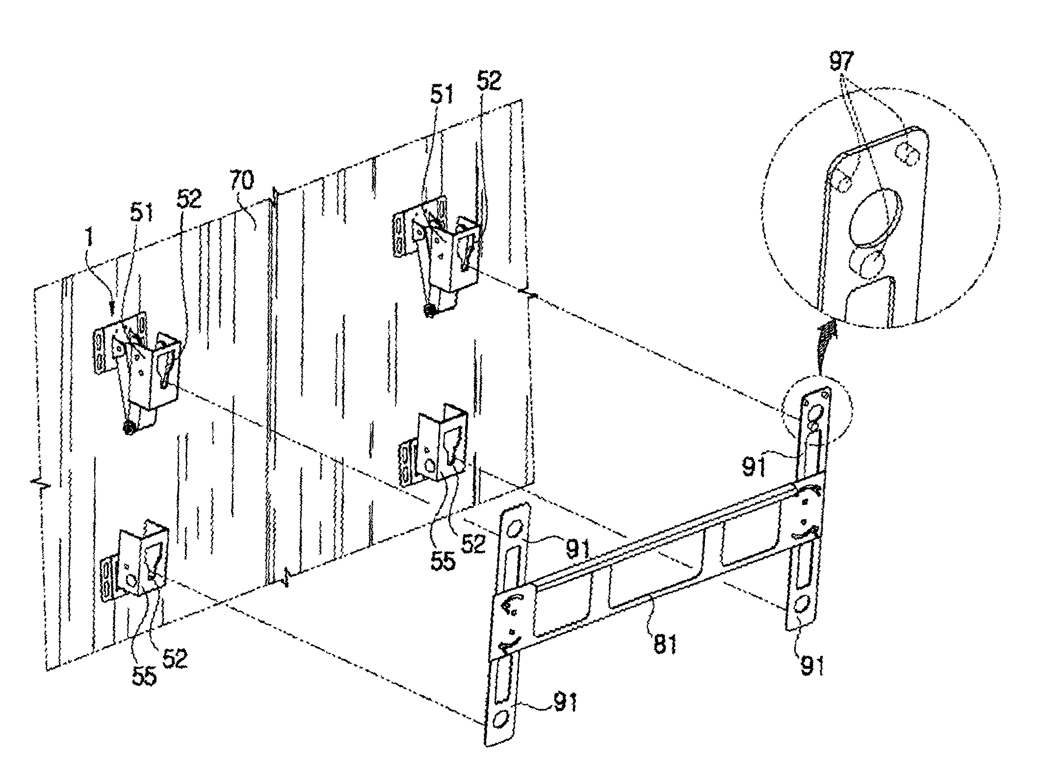
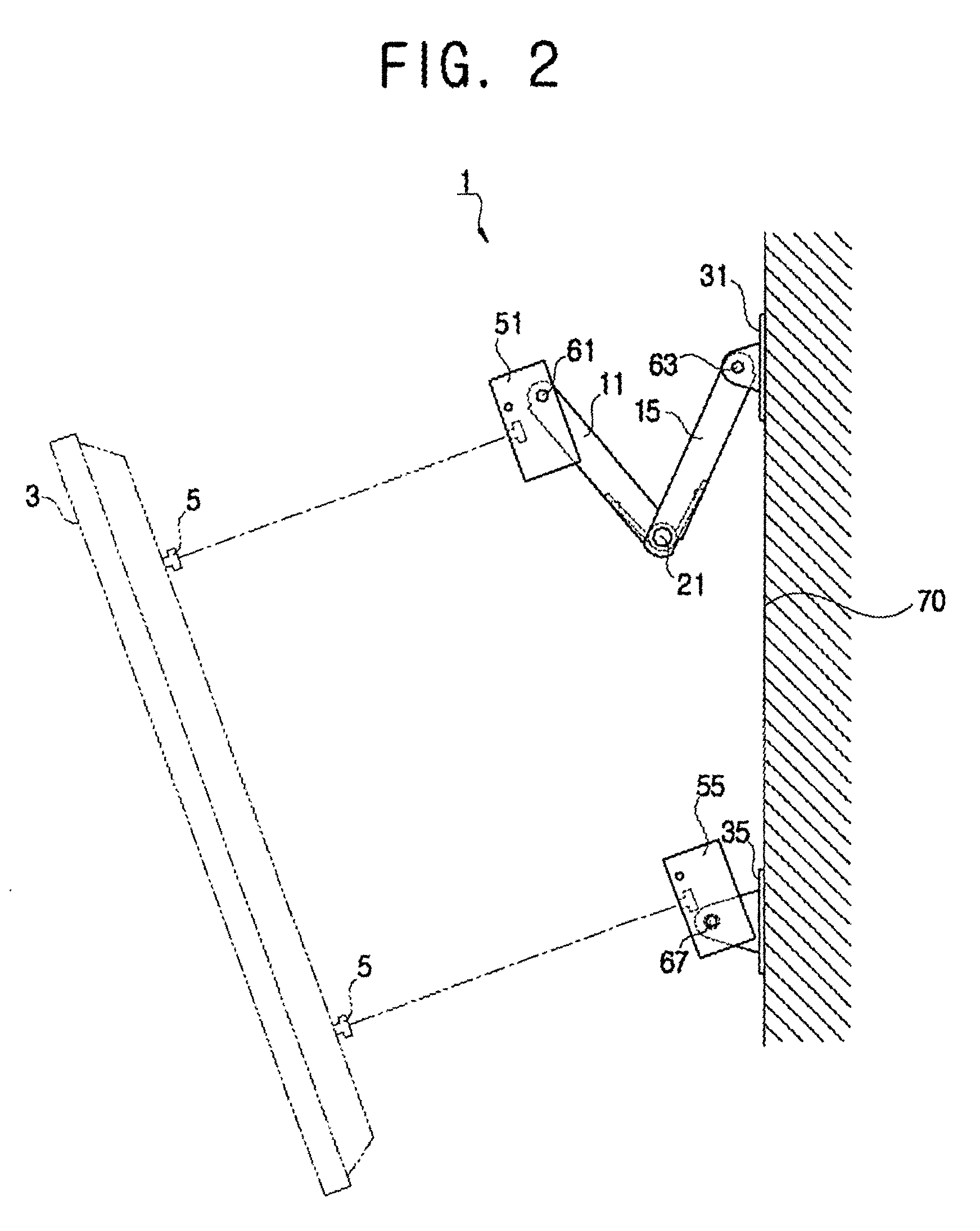
[0045]As shown in FIGS. 2 through 5, according to a first embodiment of the present invention, installation equipment 1 for a display main body is used for tiltably mounting a display main body 3 having a screen onto an installation surface such as a wall 70. The installation equipment 1 includes upper and lower main brackets 51 and 55 having a “C”-shaped cross-section and supporting a display main body 3, upper and lower supporting brackets 31 and 35 supporting the upper and lower main brackets 51 and 55 and attached to the wall 70, and a link assembly 10 provided between the upper main bracket 51 and the upper supporting bracket 31. It should be noted that, alth...


PUM


Abstract

Installation equipment for mounting a display main body onto an installation surface, includes a link assembly including a first link having a first end rotatably attached to the installation surface, a second link having a first end rotatably attached to the display main body and a second end rotatably attached to a second end of the second link, and a spring member provided in at least one joint area of the first and second links and elastically biasing the display main body toward a wall; a lower supporting bracket attached to the installation surface and rotatably supporting a lower back of the display main body; and an upper supporting bracket attached to the installation surface and supporting the link assembly. The present invention provides installation equipment and a jig which have a simple structure and are convenient for mounting the display main body onto a wall.

Description

CROSS-REFERENCE TO RELATED APPLICATION[0001]This application claims the benefit of Korean Application No. 2002-57234, filed Sep. 19, 2002, in the Korean Intellectual Property Office, the disclosure of which is incorporated herein by reference.BACKGROUND OF THE INVENTION[0002]1. Field of the Invention[0003]The present invention relates to installation equipment for a display main body and a jig for the installation equipment, and more particularly to installation equipment for a display main body and a jig for the installation equipment, which is an improvement in mounting a display main body onto a wall.[0004]2. Description of the Related Art[0005]Installation equipment for a display main body is generally used in mounting, onto a predetermined installation surface, a display main body having a screen. Recently, the screen of the display main body has been made of an LCD (liquid crystal display), a PDP (plasma display panel), etc., allowing the display main body to be thin and the s...

Claims


Application Information

Patent Timeline
Patent Type & Authority Patents(United States)
IPC IPC(8): F16M11/00G06F1/16F16M11/04F16M11/10G09F9/00H04N5/64H04N5/66
CPCF16M11/04F16M11/041F16M11/10F16M11/2021F16M11/2092H04N5/64Y10S248/923H04N5/66Y10S248/919Y10S248/922Y10S248/917F16M2200/041G06F1/16
Inventor KIM, SEONG-SOOKIM, SANG-HAK
Owner SAMSUNG ELECTRONICS CO LTD
Why Eureka
Try Eureka