
Truss for a vehicle chassis

a vehicle chassis and truss technology, applied in the field of trusses for vehicles, can solve the problems of reducing the available spacing in storage compartments and their accessibility, increasing the complexity of vehicle assembly, and increasing the manufacturing cost of trusses

Active Publication Date: 2006-08-29
VOLVO GRP CANADA
View PDF9 Cites 26 Cited by
  • Summary
  • Abstract
  • Description
  • Claims
  • Application Information

AI Technical Summary

Benefits of technology

[0007]It is an object of the present invention to provide a reinforcing truss for a vehicle chassis that allows simultaneously the creation of openings in at least one of the lateral sides of the vehicle chassis and a wide access to the storage compartments.
[0009]The present invention provides a vehicle chassis having a lower level, an intermediate level, two lateral sides subject to static and dynamic loads, and at least one storage compartment. At least one lateral side of the chassis comprises a reinforcing truss mounted between the lower and intermediate levels. The static and dynamic loads are supported by the truss. The truss includes an upper longitudinal beam mounted at the intermediate level of the chassis; a lower longitudinal beam mounted at the lower level of the chassis, the lower longitudinal beam being spaced from and parallel to the upper longitudinal beam; and at least two connecting members extending perpendicularly between the upper and lower longitudinal beams. The at least two connecting members cooperate with the upper and lower beams to define at least one bay having an outline substantially in registry with the at least one storage compartment such as to preserve wide access thereto.

Problems solved by technology

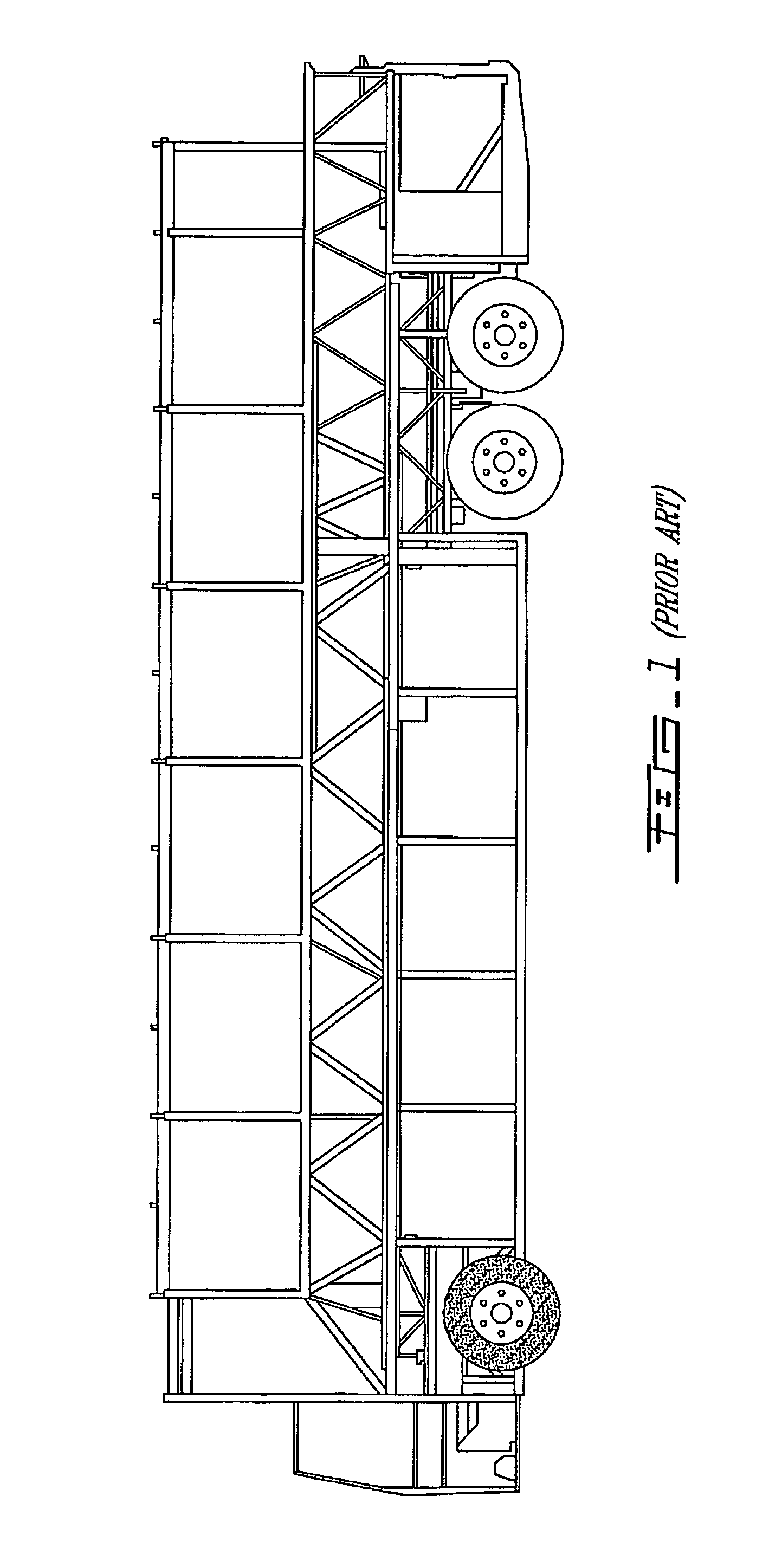
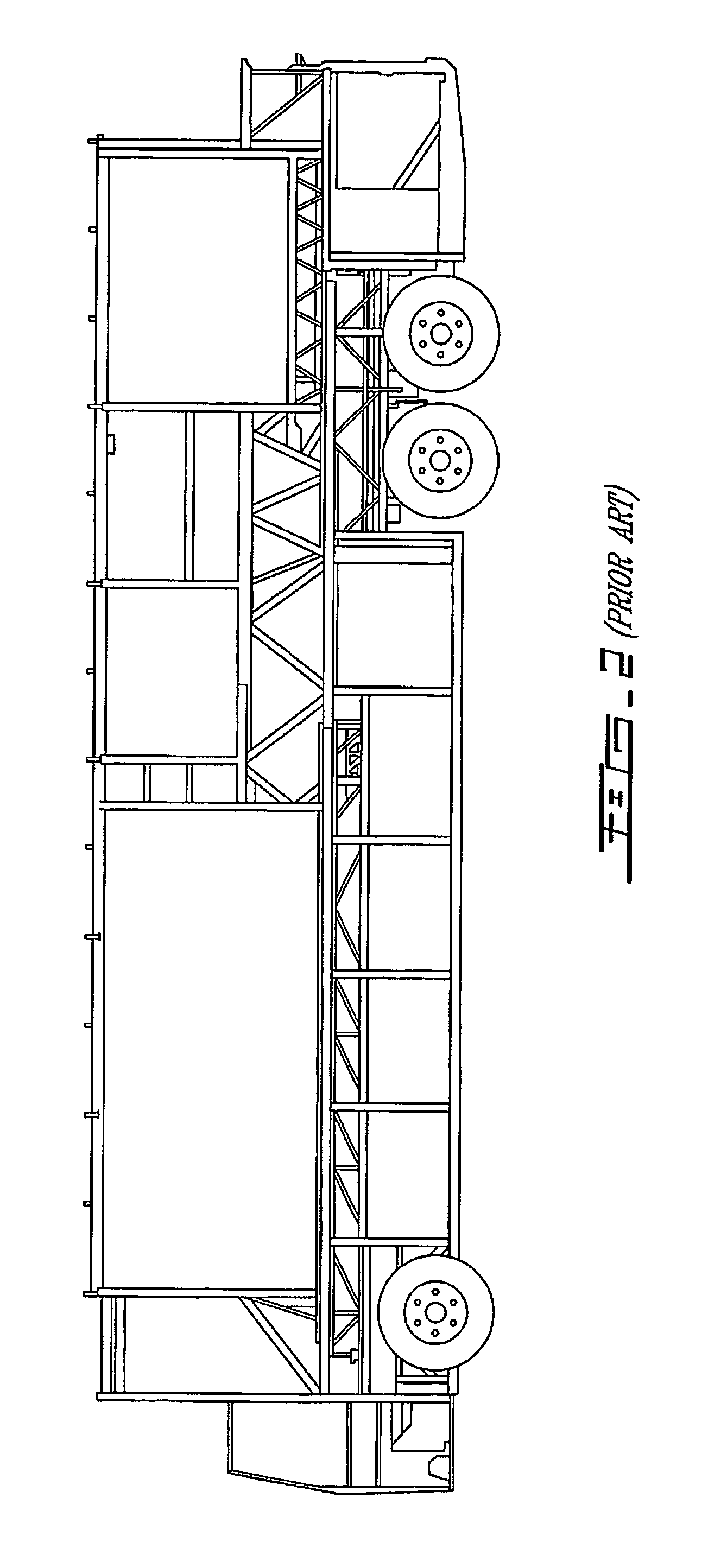
In that position, the reinforcing truss considerably reduces the available spacing in the storage compartments and their accessibility.
Moreover, this reinforcing truss can only take the stresses applied on the vehicle chassis in a static mode, i.e. when the vehicle is stationary.
These locking mechanisms are usually cumbersome inside the vehicle and increase the manufacturing costs, the vehicle weight, and the complexity to assemble the vehicle.

Method used


Image

  • Truss for a vehicle chassis
  • Truss for a vehicle chassis
  • Truss for a vehicle chassis

Examples


Embodiment Construction

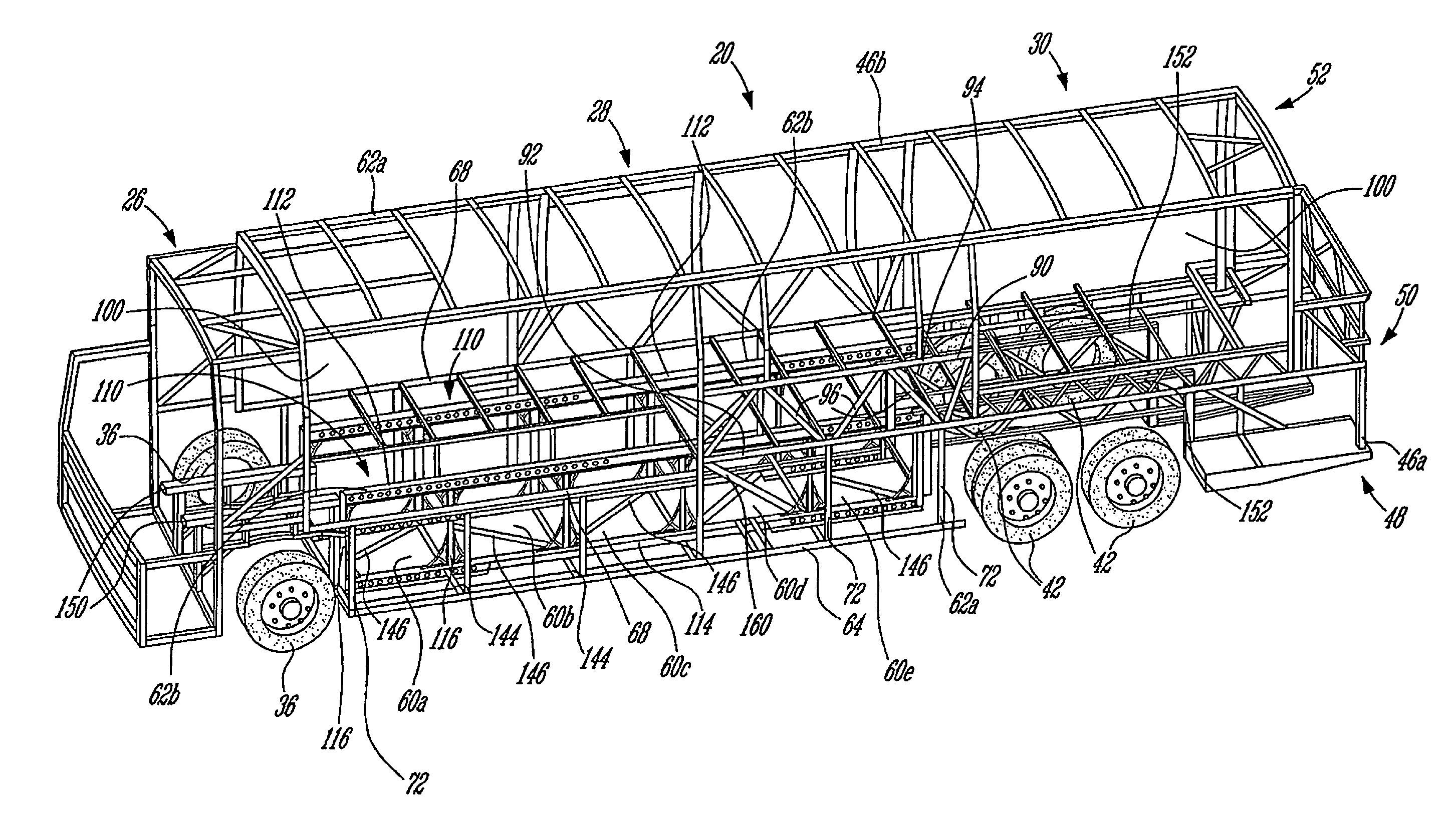
[0023]Referring simultaneously to FIGS. 3 and 4, there is shown an embodiment of a vehicle chassis 20 having a front chassis component 26, a central chassis component 28, and a rear chassis component 30. The delimitation between the front and central chassis components 26, 28 and the central and rear chassis components 28, 30 are respectively the front wheels 36 and the rear wheels 42 of the vehicle.

[0024]The chassis 20 has two lateral sides 46a, 46b, parallel to each other, and three levels: a lower level 48, an intermediate level 50, and an upper level 52. The passenger floor (not shown) is mounted at the intermediate level 50 while the roof of the vehicle (not shown) is mounted at the upper level 52. Several storage compartments 60a, 60b, 60c, 60d, 60e are located between the lower level 48 and the intermediate level 50 in the central chassis component 28. A storage floor (not shown) is mounted at the lower level 48. The storage compartments 60a, 60b, 60c, 60d, 60e are usually id...


PUM


Abstract

The present invention relates to a vehicle chassis having a lower level, an intermediate level, and two lateral sides subject to static and dynamic loads. At least one lateral side comprises a reinforcing truss mounted between the lower and intermediate levels for supporting the static and dynamic loads. The truss includes an upper longitudinal beam mounted at the intermediate level of the chassis; a lower longitudinal beam mounted at the lower level, spaced from and parallel to the upper longitudinal beam; and at least two connecting members extending perpendicularly between the upper and lower longitudinal beams. The connecting members cooperate with the upper and lower beams to define at least one bay having an outline substantially in registry with the outline of the at least one storage compartment.

Description

BACKGROUND OF THE INVENTION[0001]1) Field of the Invention[0002]The present invention relates to a truss for a vehicle chassis and, more particularly, to a chassis for large vehicles having an opening in one of their lateral sides. It also relates to a method to reinforce a vehicle chassis.[0003]2) Description of the Prior Art[0004]Large motorized vehicles, such as recreational vehicles (RVs), motor homes, and busses, have a chassis on which the body and the mechanical workings of the vehicle, such as the suspension, the motor, and the drive train, are mounted.[0005]An important portion of the bending rigidity (or flexural rigidity) of a conventional vehicle chassis is ensured by a lateral structural truss (FIG. 1) mounted above the passenger floor on each lateral side of the vehicle chassis. The lateral structural truss usually consists of a lower beam mounted at the height of the passenger floor and an upper beam mounted parallel to the lower beam and above the latter. The lower a...

Claims


Application Information

Patent Timeline
Patent Type & Authority Patents(United States)
IPC IPC(8): B60R5/00
CPCB62D31/02B62D21/18
Inventor BEAUDRY, HUGUESDELBRIDGE, GREGORY RICHARD
Owner VOLVO GRP CANADA
Learn More