Hole-saw assembly including two hole-saws

a technology of hole-saw assembly and hole-saw head, which is applied in the direction of sawing apparatus, boring/drilling apparatus, turning apparatus, etc., can solve the problems of double-threaded boss, inability to connect two hole-saws to a single mandrel at once, and the number of problems encountered

Active Publication Date: 2006-08-29
KEIGHTLEY KYM JOHN
View PDF7 Cites 74 Cited by
  • Summary
  • Abstract
  • Description
  • Claims
  • Application Information

AI Technical Summary

Benefits of technology

[0031]Preferably said annulus is rotatable from a first biased position to a second position, whereby when the annulus is in the first position, each locking means engages corresponding drive pins and thereby prevents them from longitudinal movement, and when the annulus is in the second position, each locking means disengages corresponding drive pins and thereby allows for movement in the longitudinal direction.
[0045]Preferably said annulus is rotatable from a first biased position to a second position, whereby when the annulus is in the first position, each locking means engages corresponding drive pins and thereby prevents them from longitudinal movement, and when the annulus is in the second position, each locking means disengages corresponding drive pins and thereby allows for movement in the longitudinal direction.

Problems solved by technology

A number of problems have been encountered using the abovementioned hole-saw assemblies.
Firstly, the double-threaded boss, although useful in connecting different sized hole-saws simultaneously, is quite cumbersome in that the user may need to screw on and unscrew a number of different hole-saws in a single application.
Secondly, the connection means mentioned above, although simplifying the method of connecting the hole-saw to the mandrel, does not allow two hole-saws to be connected to a single mandrel at once.

Method used


Image

  • Hole-saw assembly including two hole-saws
  • Hole-saw assembly including two hole-saws
  • Hole-saw assembly including two hole-saws

Examples


third embodiment

[0089]A rotational force is required to rotate each annulus to its second position wherein each of the corresponding apertures between mandrel 16 and annulus 22 or 24 become coaxially aligned. When the apertures of an annulus become aligned with the apertures of the mandrel 16, the drive pins 50 or 52 of a hole-saw 12 or 14 are able to be inserted into or withdrawn from the annulus. Each annulus 22 and 24 is biased in its first position, that is, in its misaligned positioned. When the drive pins have been engaged with an annulus, the annulus will have returned to its biased first position, as will become obvious. The way in which each annulus is biased is by way of a simple pin 80 and spring 82 combination which will be explained in greater detail when describing the

[0090]The way in which aperture pairs 78 and 80 of the annuluses engage with corresponding drive pin pairs 50 and 52 of the hole-saws is not shown in the drawings with respect to the first and second embodiments, but can...

second embodiment

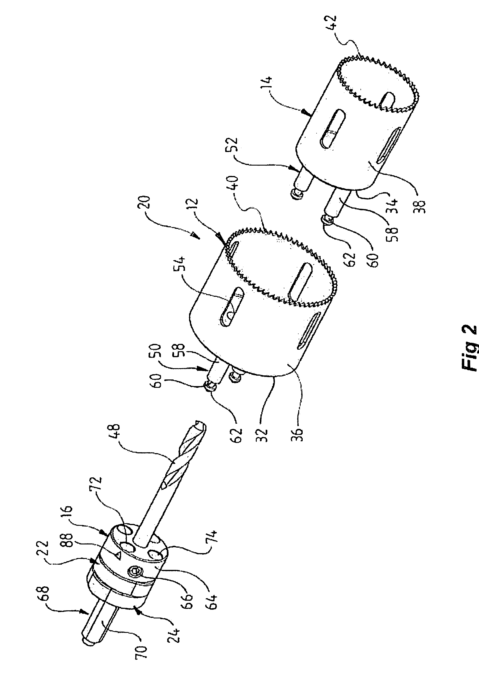
[0094]The skilled addressee will now appreciate that the hole-saw assembly 20 according to the invention enables for the very quick mounting and demounting of hole-saws of different diameter to a mandrel 16 that is already mounted in a drill.

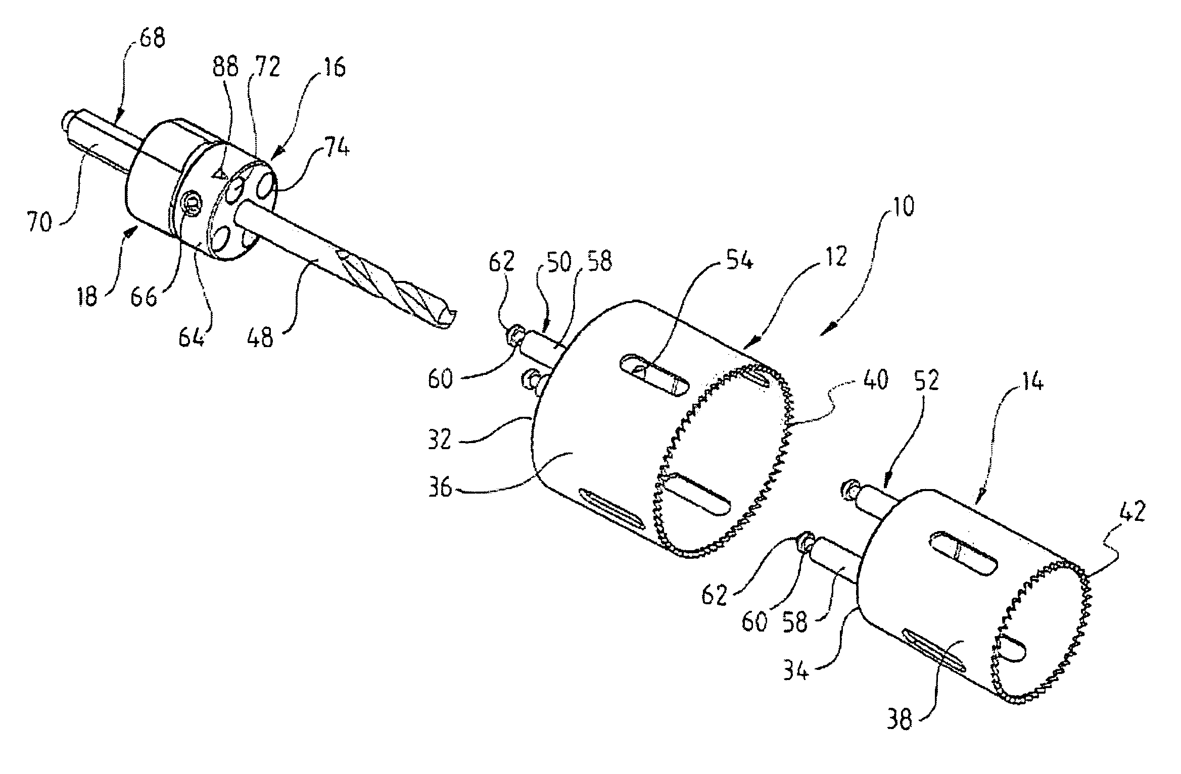
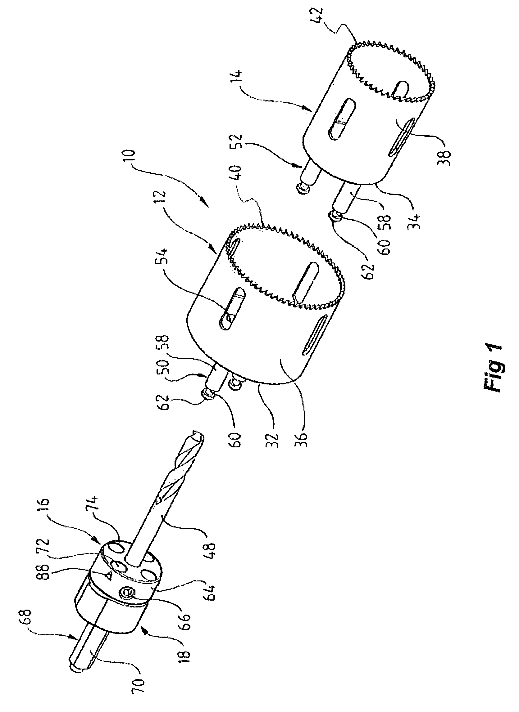
[0095]Referring back now to FIG. 1 and hole-saw assembly 10 which includes only a single annulus 18 according to a first and broadest aspect of the invention. The single annulus 18 comprises two adjacent locking mechanisms almost identical to that of the second embodiment, except the locking mechanisms are not rotatable independently of the other. This mechanism will not be explained in any great detail, but it is important to note that in having two locking mechanisms in an integral unit such as annulus 18 means that each locking means moves from the first to the second position simultaneously. This means that if hole-saw 12 is engaged within the second locking mechanism within the annulus 18, then when the second hole-saw is inserted, the enti...

fifth embodiment

[0100]A problem with the above three embodiments is the fact that one must identify which aperture pair the first hole-saw should be inserted, for example, by marker 88 which is aligned with the aperture pair to which the second locking mechanism applies. This problem is overcome according to a fourth and fifth embodiment of the present invention.

[0101]FIGS. 11 and 12 illustrate a hole-saw assembly 110 including a mandrel 16 and a double annulus configuration similar to that of the second embodiment. The first and second annuluses 112 and 114 however each include two pairs of engaging apertures, that is, annulus 112 includes engaging aperture pair 116 and 118 whilst annulus 114 includes engaging aperture pair 120 and 122. Further, each of the drive pins of drive pin pairs 124 and 126 of hole-saws 128 and 130 respectively include a first 132 and a second 134 chamfered cap. In this embodiment, the length of the mandrel body 64 is the same length as that of the drive pin columns 136, s...


PUM

PropertyMeasurementUnit
diameteraaaaaaaaaa
lengthaaaaaaaaaa
distanceaaaaaaaaaa

Abstract

The present invention relates to an improved hole-saw assembly and in particular, to a mandrel engageable by a drill and including at least one locking ring or annulus that allows for the base of two hole-saws of different diameter to be quickly and easily mountable and demountable from the mandrel. The hole-saw assembly includes a first hole-saw having a base that includes a pair of drive-pins extending outwardly therefrom and a pair of apertures for insertion therethrough of the drive pins of a second hole-saw. The drive pin pairs are then inserted through corresponding apertures in the mandrel to engage an annulus coupled to the mandrel. The present invention provides for each drive pin to be engaged by the annulus despite the difference in longitudinal length of the drive pins beyond the base of the first hole-saw. The hole-saws are snap-fit within the annulus and may be disengaged by simply rotating the annulus to a second position. A further embodiment of the present invention further allows one to insert the hole-saws into any one of the mandrel insertion points without being concerned about whether it contains the correct engaging means or not. A still further embodiment of the invention prevents slight longitudinal movement which is known to occur when the hole-saws are coupled to the mandrel.

Description

CROSS-REFERENCE TO RELATED APPLICATIONS[0001]This application claims the benefit of AU 2003904524, filed 22 Aug. 2003 by the present inventor.FEDERALLY SPONSORED RESEARCH[0002]Not ApplicableSEQUENCE LISTING OR PROGRAM[0003]Not ApplicableBACKGROUND OF THE INVENTION—FIELD OF THE INVENTION[0004]The present invention relates to an improved hole-saw assembly and in particular, to a mandrel engageable by a drill and including at least one locking ring or annulus that allows for the base of two hole-saws of different diameter to be quickly and easily mountable and demountable from the mandrel.BACKGROUND OF THE INVENTION[0005]Hole-saws typically include a flat, solid base which provides support for a cylindrically shaped member protruding therefrom that includes cutting teeth at its circular end. The base is generally locked by a drill mandrel and includes a central bore through which a pilot drill, also locked by the mandrel, may pass. Some hole-saw bases are known to include multiple diam...

Claims


Application Information

Patent Timeline
Patent Type & Authority Patents(United States)
IPC IPC(8): B23B51/04B27B5/12B27B33/18B27G15/00
CPCB23B51/0473B23B2240/04B23B2270/14Y10T408/8957Y10T408/95Y10T408/895Y10T408/8967B27B5/12B27G15/00
Inventor KEIGHTLEY, KYM JOHN
Owner KEIGHTLEY KYM JOHN
Why Eureka
Try Eureka