Method and apparatus for measuring beam spot of scanning light

a scanning light and beam spot technology, applied in the field of methods and apparatus for measuring beam spots of scanning light, can solve the problems of inability to perform continuous evaluation throughout the primary scanning direction, inability to obtain accurate results, and apparatuses that can only measure stationary light beams

Inactive Publication Date: 2006-08-29
SEIKO EPSON CORP
View PDF13 Cites 8 Cited by
  • Summary
  • Abstract
  • Description
  • Claims
  • Application Information

AI Technical Summary

Benefits of technology

[0038]an actuator, which integrally moves the plate and the optical sensor within the first range in the first direction at a second velocity which is sufficiently lower than the first velocity, so that a peak value of an optical power of light passing through the slit every time when the deflected light beam crosses the slit being moved, thereby causing the optical sensor to output peak values at plural positions in the first direction; and

Problems solved by technology

However, these apparatuses can measure only a stationary light beam.
Further, in a case where the spot shape is different between the stationary state and the scanned state, accurate results cannot be obtained.
However, also in this case, a mechanism for accurately positioning a beam in the light receiving portion of a sensor is necessary and a time is required for carrying out a positioning operation.
In the prior art described above, the inclined angle of the spot can be measured in a specific position in the primary scanning direction, but continuous evaluation throughout in the primary scanning direction cannot be executed.
Even if a plurality of measuring points are provided, long time is required for the measurement.
Even if measuring data are quantitatively obtained, since numeral data are merely enumerated, it is hard to instinctively and visually recognize a problematic situation.
Furthermore, it is impossible to measure a large number of measuring items once at a time.

Method used


Image

  • Method and apparatus for measuring beam spot of scanning light
  • Method and apparatus for measuring beam spot of scanning light
  • Method and apparatus for measuring beam spot of scanning light

Examples


first embodiment

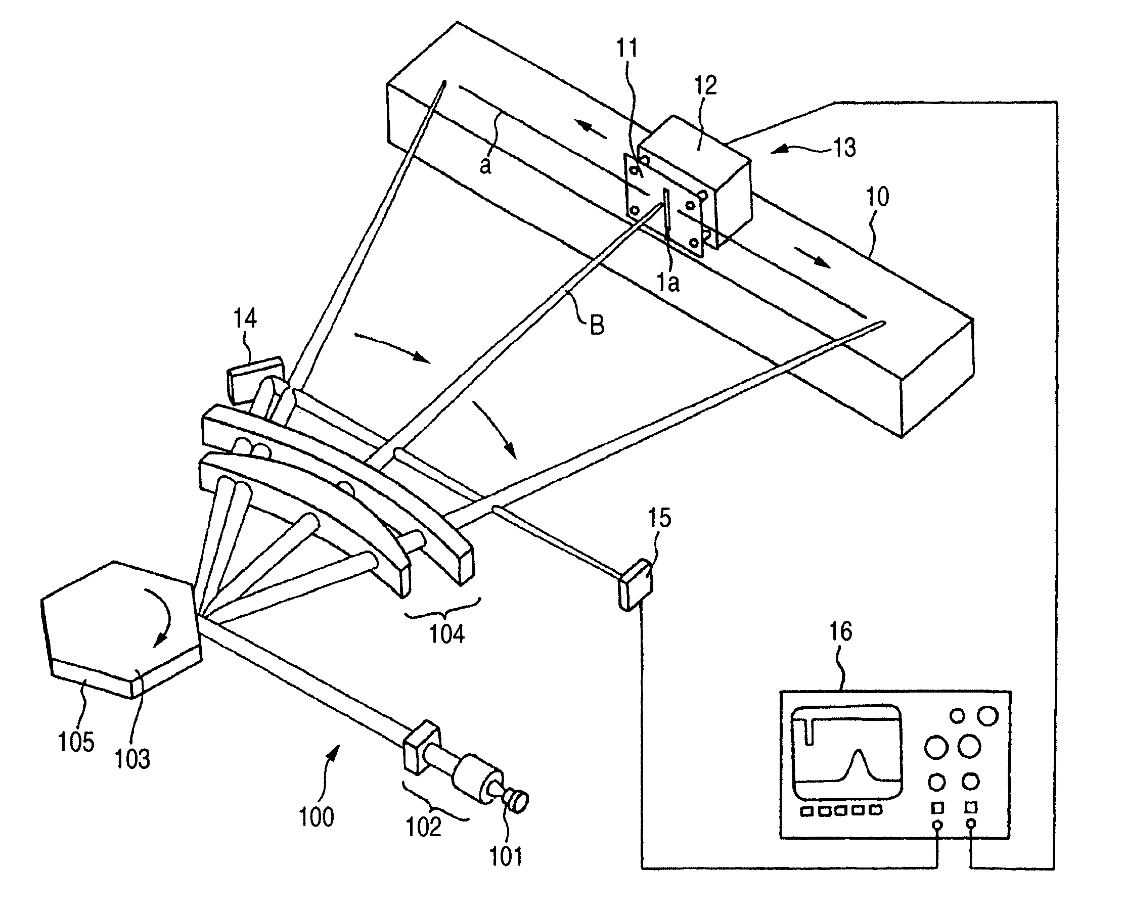
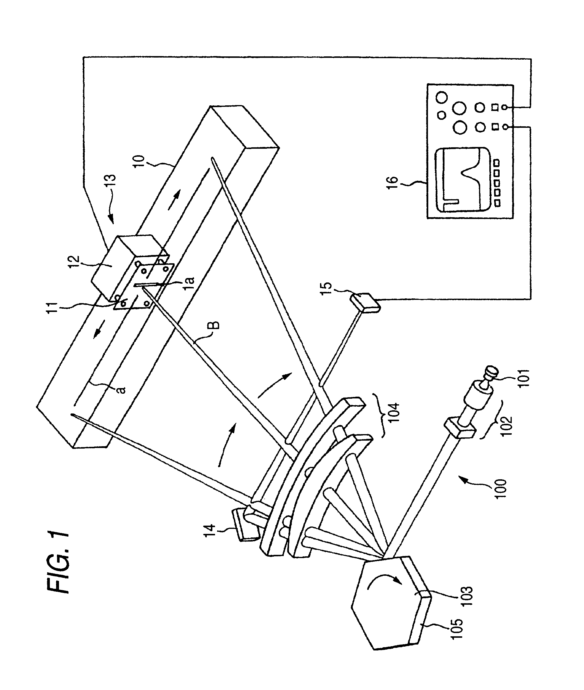
[0063]FIG. 1 shows the invention which is an apparatus for measuring a focal condition of a scanning light beam. In this embodiment, a light scanning device 100 comprises a light source 101, a lens unit 102, a polygon mirror 103 and a scanning optical system 104. A light beam emitted from the light source 101 is converted into a parallel light beam by the lens unit 102, and incident on the reflection face 105 of the polygon mirror 103. The light beam is reflected and deflected by the reflection face 105 is converted into a scanning light beam B deflected in the direction of an arrow through the scanning optical system 104, and is focused on a scanned face. In a case where it is adopted an optical system for correcting a pyramidal angle error of a polygon mirror, the light beam emitted from the light source 101 is converted into a parallel light beam relative to a direction perpendicular to a rotation axis of the polygon mirror while being converted into a light beam to be focused in...

second embodiment

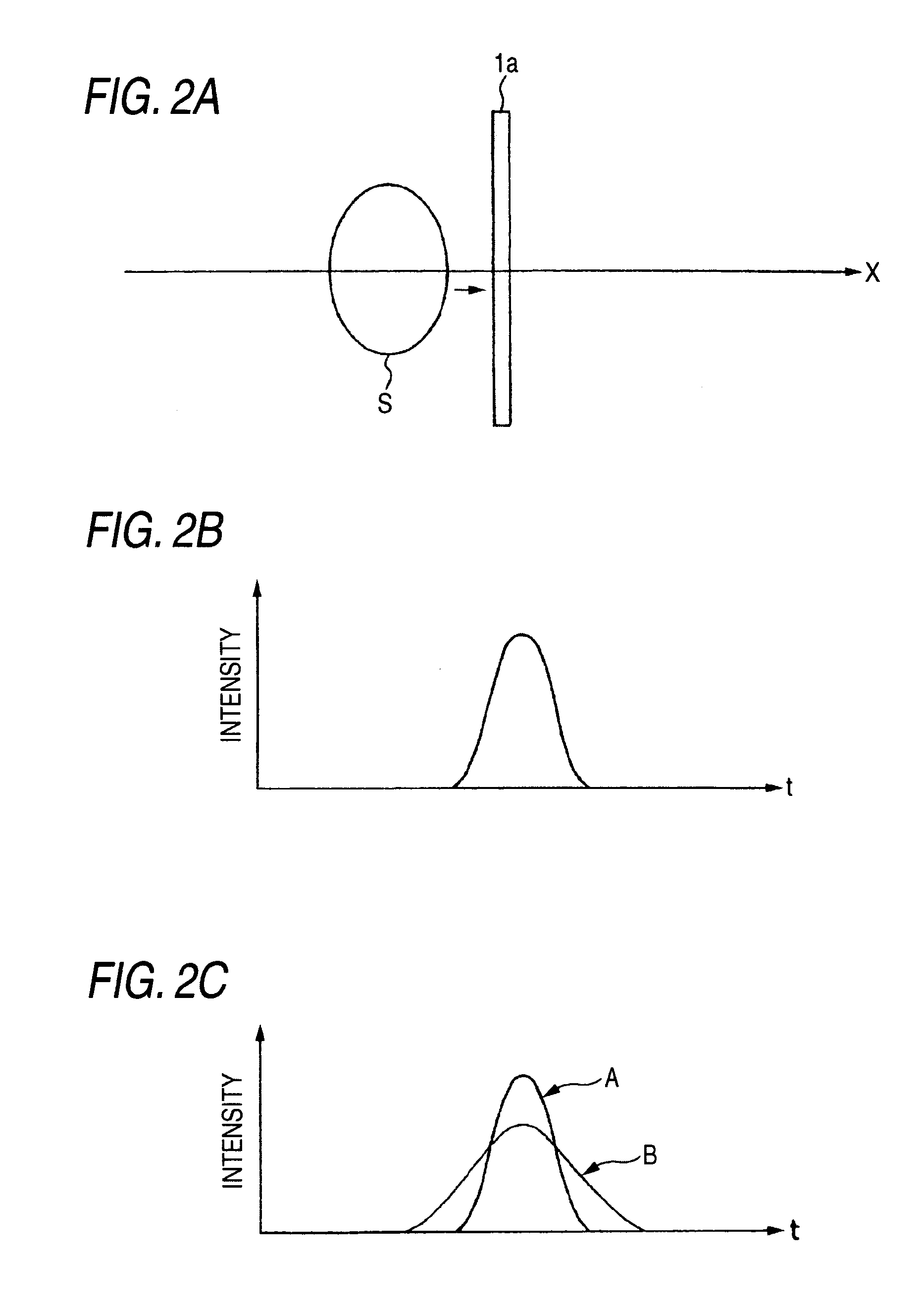
[0073]In this embodiment, the slit 1a is extended in the secondary scanning direction which is orthogonal to the x-axis. However, the extending direction of the slit 1 a may be inclined relative to the primary scanning direction. In this case, a spot size of the beam spot S in the oblique direction relative to the primary scanning direction or an inclined angle of the beam spot S can be continuously measured and evaluated. This case will be described below in detail as the invention.

[0074]As shown in FIG. 6, in the arrangement of FIG. 1, there is used a slit plate 11 in which a slit 1X and a slit 1Y are arranged in the primary scanning direction. The slit 1X extends in a direction inclined by +45 degrees (clockwise) from the secondary scanning direction. The slit 1Y extends in a direction inclined by −45 degrees (counterclockwise) from the secondary scanning direction. Herein, the slit widths in the primary scanning direction of the slits 1X and 1Y are smaller than a dimension in th...

third embodiment

[0081]In the above embodiments, the slit 1a provided on the slit plate 11 has a smaller width than the dimension of the beam spot S. However, if a slit 1b having a greater width than a dimension in the primary scanning direction of the beam spot S is provided as shown in FIG. 11A, it is possible to detect the power of the beam spot S. This case will be described below in detail as the invention. The slit 1b has a width in the primary scanning direction (x-axis) which is greater than the dimension of the beam spot S as described above. The moving velocity of the slit plate 11 is set to be sufficiently lower than that of the scanning light beam B. In a case where the beam spot S is moved over the slit 1b in the x direction, an optical power waveform obtained from the optical sensor 12 provided behind the slit plate 11 is shown in FIG. 11B, and a peak value P represents a value which is proportional to the power of the scanning light beam B without depending on the focal condition of t...


PUM


Abstract

In order to measure a characteristics of a light beam which is repetitively deflected by a light scanning device within a first range in a first direction at a first velocity, there is provided a plate formed with at least one slit extending in a direction angled from the first direction and having a constant width. The plate is moved within the first range in the first direction at a second velocity which is sufficiently lower than the first velocity. A peak value of an optical power of light passing through the slit every time is detected when the deflected light beam crosses the slit being moved, thereby obtaining peak values at plural positions in the first direction. The peak values are displayed on a screen collectively in such a manner that positions on the screen correspond to the positions in the first direction.

Description

BACKGROUND OF THE INVENTION[0001]The present invention relates to a method and an apparatus for measuring a beam spot of scanning light, and more particularly to a method and an apparatus capable of continuously measuring and displaying properties of the scanning light such as a shape of the beam spot, which change in a primary scanning direction and a light advancing direction.[0002]The followings are well-known techniques for measuring the properties of the scanning light such as the beam spot shape.[0003]It is on sale “Beam Alyzer” manufactured by the Melles Griot Inc., wherein a knife edge is provided on a rotary drum, and a section profile and a spot size of a beam spot are measured on the basis of optical power variation when an incident light beam crosses the knife edge. It is also on sale “Beam Scan” manufactured by Photon Inc., wherein a focal condition of an incident light beam is similarly measured by a narrow slit provided on a rotary drum.[0004]However, these apparatuse...

Claims


Application Information

Patent Timeline
Patent Type & Authority Patents(United States)
IPC IPC(8): H01J3/14H01J40/14H01J5/16B41J2/44G01B11/00G01J1/00G01J1/02G02B26/10H01J37/08
CPCB41J2/471G02B26/127G01J1/4223G01J1/0437
Inventor INOUE, NOZOMUSOWA, TAKESHIMITSUI, YOICHI
Owner SEIKO EPSON CORP
Why Eureka
Try Eureka