
Rotor assembly for a permanent magnet power electric machine

a permanent magnet power electric machine and rotor assembly technology, applied in the direction of dynamo-electric machines, magnetic circuit rotating parts, magnetic circuit shapes/forms/construction, etc., can solve the problem that the configuration of the rotor assembly is not readily convertible to other types or sizes of motors, create unique balancing issues with respect to vibration modes, etc., to achieve the effect of reducing the weight of the rotor assembly, and reducing the weight of the ro

Active Publication Date: 2006-08-29
CONTINENTAL AUTOMOTIVE SYST INC
View PDF29 Cites 25 Cited by
  • Summary
  • Abstract
  • Description
  • Claims
  • Application Information

AI Technical Summary

Benefits of technology

[0011]The assemblies and components described herein provide a variety of ways to reduce the weight of a rotor assembly for an electric machine. Reducing the weight of the rotor assembly permits the rotor to rotate at higher speeds while meeting specific mass targets for electric machines in the automotive industry.

Problems solved by technology

The inclusion of the central web extending radially from the shaft creates unique balancing issues with respect to vibration modes.
Thus, although the Toyota Prius shaft provides dome marginal weight reduction benefits, the configuration of the rotor assembly is not readily convertible to other types or sizes of motors.

Method used


Image

  • Rotor assembly for a permanent magnet power electric machine
  • Rotor assembly for a permanent magnet power electric machine
  • Rotor assembly for a permanent magnet power electric machine

Examples


Embodiment Construction

[0032]In the following description, certain specific details are set forth in order to provide a thorough understanding of various embodiments of the present assemblies, devices and systems. However, one skilled in the relevant art will recognize that the present assemblies, devices and systems may be practiced without one or more of these specific details, or with other methods, components, materials, etc. In other instances, well-known structures associated with electric machines have not been shown or described in detail to avoid unnecessarily obscuring descriptions of the embodiments of the present assemblies, devices and systems.

[0033]Unless the context requires otherwise, throughout the specification and claims which follow, the word “comprise” and variations thereof, such as, “comprises” and “comprising” are to be construed in an open, inclusive sense, that is as “including, but not limited to.”

[0034]Reference throughout this specification to “one embodiment” or “an embodimen...


PUM


Abstract

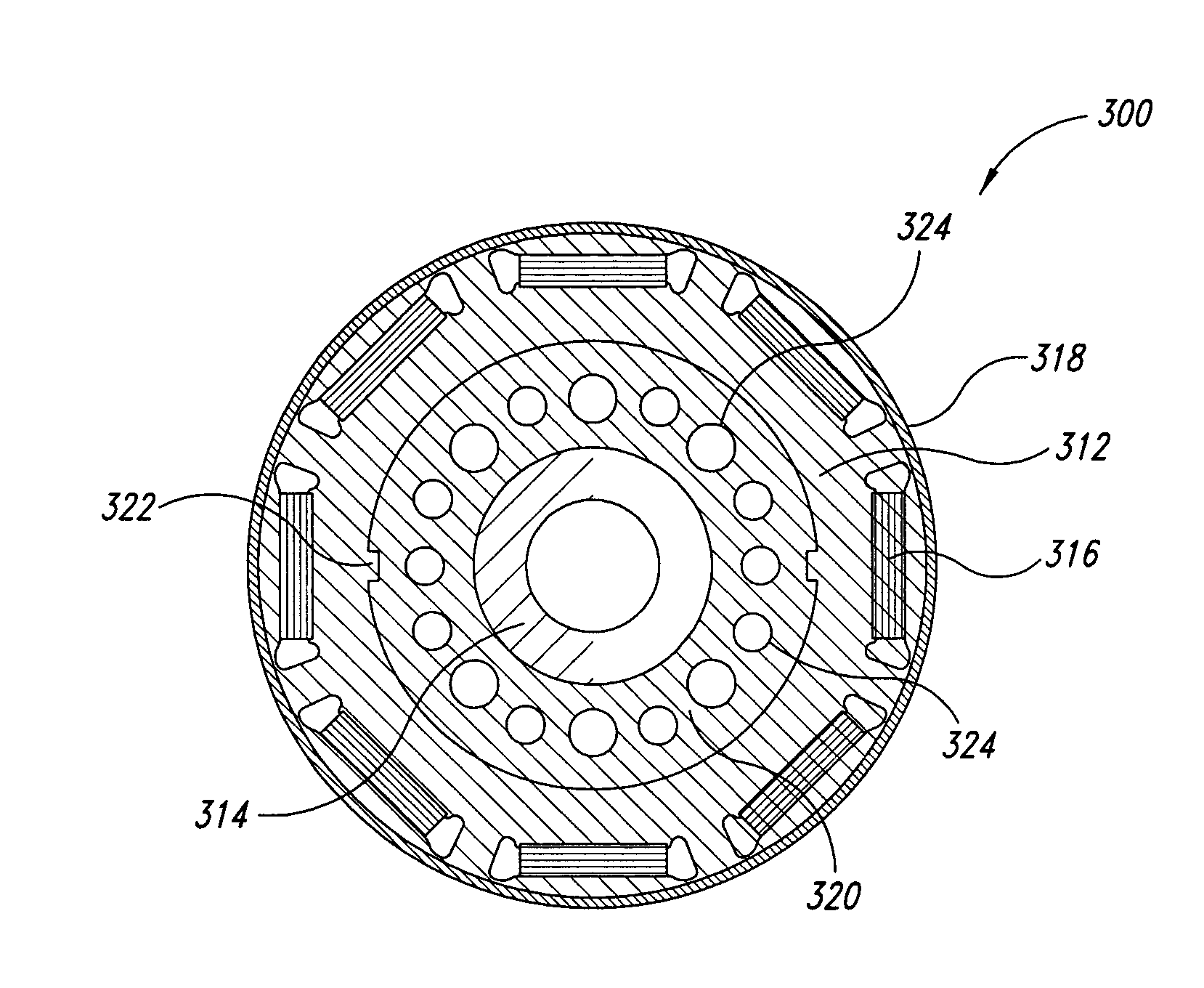
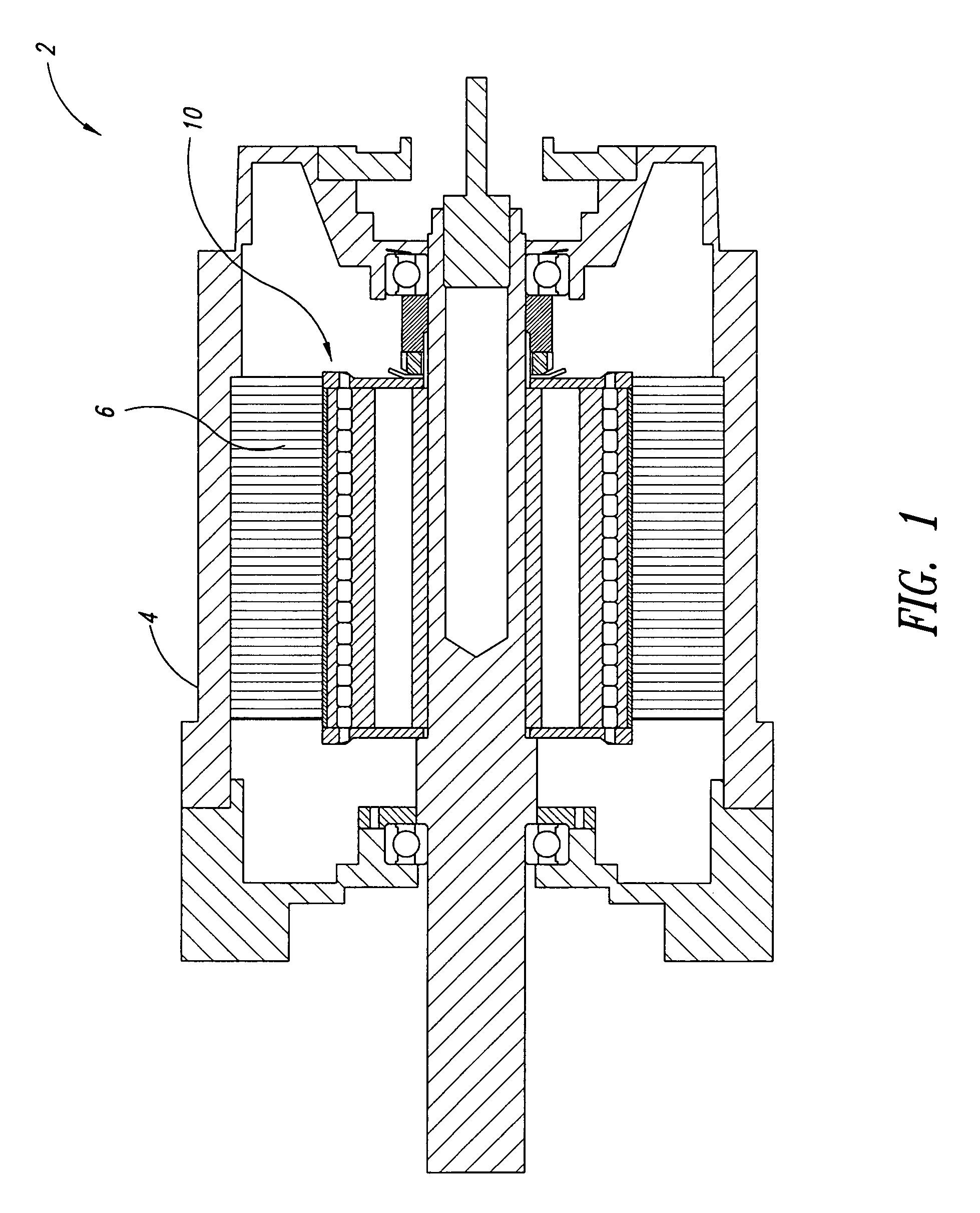
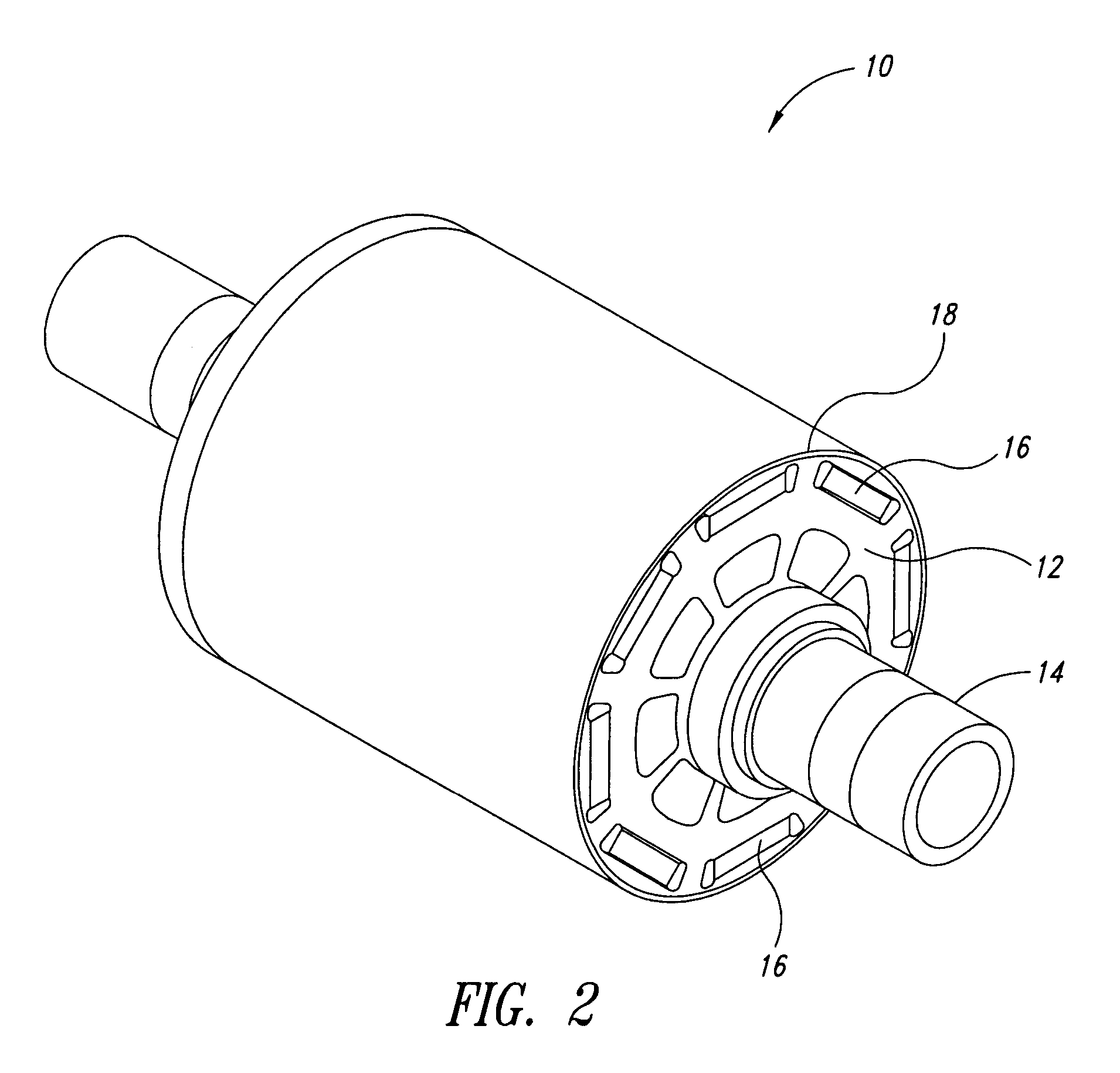
A rotor assembly for use in an electric motor or generator where the mass of the rotor assembly is reduced with respect to conventional rotor assemblies. In addition, the rotor assembly is configured to be scalable to different sized electric motors. Within the rotor assembly, the rotor hub, the shaft, and the permanent magnets can independently or collectively be modified to have a reduced mass. In one aspect, a portion of the rotor hub adjacent to the shaft is configured with passages and spokes. In another aspect, an intermediate hub with lightening holes is provided between the shaft and the rotor hub. In yet another aspect, a large diameter hollow shaft replaces a portion of the rotor hub. In yet another aspect, the permanent magnets are configured to have an arc-shape, which permits the thickness of the magnets to be reduced without reducing the efficiency of the magnets.

Description

[0001]This application claims the benefit of U.S. Provisional Patent Application No. 60 / 608,930 filed on Jul. 30, 2004, which is incorporated herein by reference in its entirety.BACKGROUND OF THE INVENTION[0002]1. Technical Field[0003]The present disclosure relates generally to electric machines, for example, permanent magnet motors and generators.[0004]2. Description of the Related Art[0005]Electric machines, such as electric motors and generators, are used in many applications, including those ranging from electric vehicles to domestic appliances. Improvements in machine performance, reliability, efficiency, and power density for all types of electric motors are desirable.[0006]An electric machine converts electrical or electromagnetic energy into mechanical energy or conversely converts mechanical energy into electrical or electromagnetic energy.[0007]The permanent magnets used in rotor assemblies are disposed within axially extending pockets. The pockets are typically formed nea...

Claims


Application Information

Patent Timeline
Patent Type & Authority Patents(United States)
IPC IPC(8): H02K1/22
CPCH02K1/278
Inventor ONG, RAYMONDALLEN, TIMOTHY J.DAVIS, ROY I.TESCH, TOD R.
Owner CONTINENTAL AUTOMOTIVE SYST INC
Learn More