Deactivating a data tag for user privacy or tamper-evident packaging

a data tag and privacy technology, applied in the field of radio frequency identification (rfid) tags, can solve the problems of consumer privacy, delay in several efforts to implement rfid, and existing systems that do not use rfid tags to ensure the proper loading of the devi

Active Publication Date: 2006-08-29
BUFFALO PATENTS LLC
View PDF93 Cites 1438 Cited by
  • Summary
  • Abstract
  • Description
  • Claims
  • Application Information

AI Technical Summary

Benefits of technology

[0008]In order to solve these and other needs in the art, the inventors hereof have succeeded at designing systems and methods for load sensing, orientation sensing, detection of product and package tampering, and user privacy with radio frequency identification (RFID) technology. Embodiments of the present invention include RFID tags that include a load-sensitive mechanical switch capable of enabling communication of a signal when a package is not properly oriented or when the package is not loaded with product. Thus, multifunctional RFID chips assist not only in tracking goods, but also in ensuring proper loading or orientation of products and packaging.

Problems solved by technology

However, existing systems do not use RFID tags to ensure the proper loading or orientation of products and packaging.
Further, a major roadblock to the commercial implementation of RFID technology has been consumer privacy.
Public fears about the potential misuse of the information that could be obtained by tracking purchases with RFID have resulted in delays in several efforts to implement RFID.
However, killing the tag may eliminate all or some of the functionality and the benefits that can be obtained through RFID technology (e.g., consumer benefits such as automated registration of products, automated interactions of other articles with the purchased items, consumer tracking and cataloging of purchased articles using RFID systems, and automated safety systems).
Many consumers are not trained in detecting tampering or fail to recognize that an indicator for tampering has been activated.
In general, for most products, there have not been successful methods brought to the marketplace for automatically detecting tampering and eliminating tampered products before the product is sold to the consumer.
For example, the use of RFID technology in this manner detects tampering with electricity meter boxes associated with electricity theft.
The existing technology, however, is based on single RFID tag systems in labels in which the tag is permanently disabled by tampering or in which tampering causes a new code to be written to an expensive writable RFID tag.

Method used


Image

  • Deactivating a data tag for user privacy or tamper-evident packaging
  • Deactivating a data tag for user privacy or tamper-evident packaging
  • Deactivating a data tag for user privacy or tamper-evident packaging

Examples


Embodiment Construction

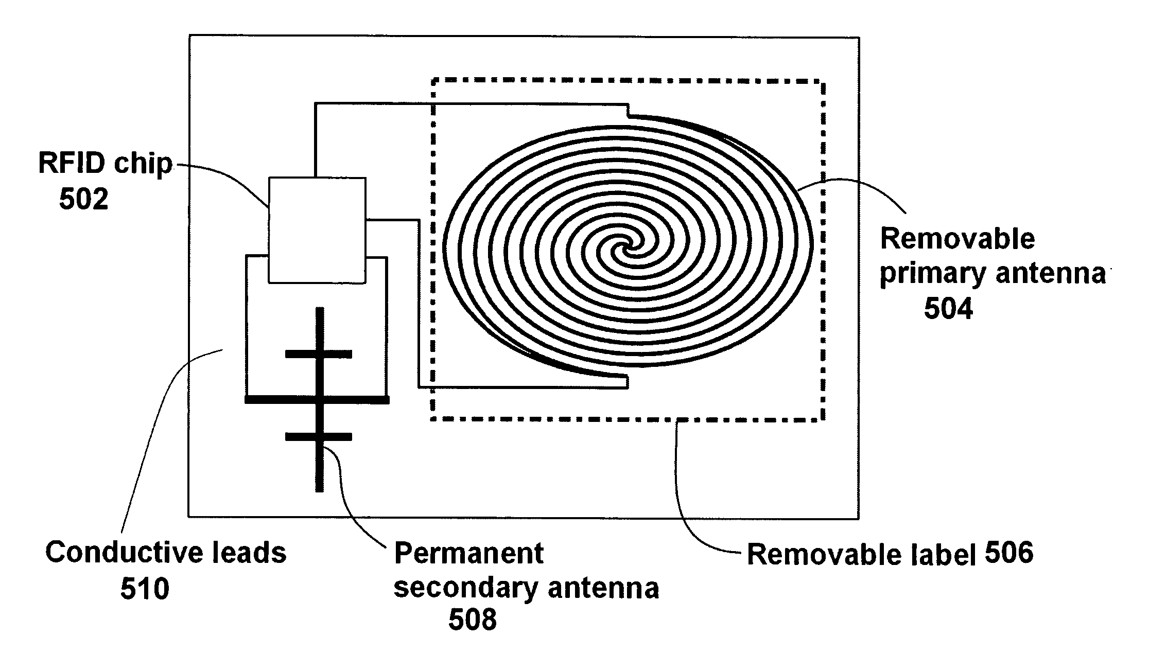
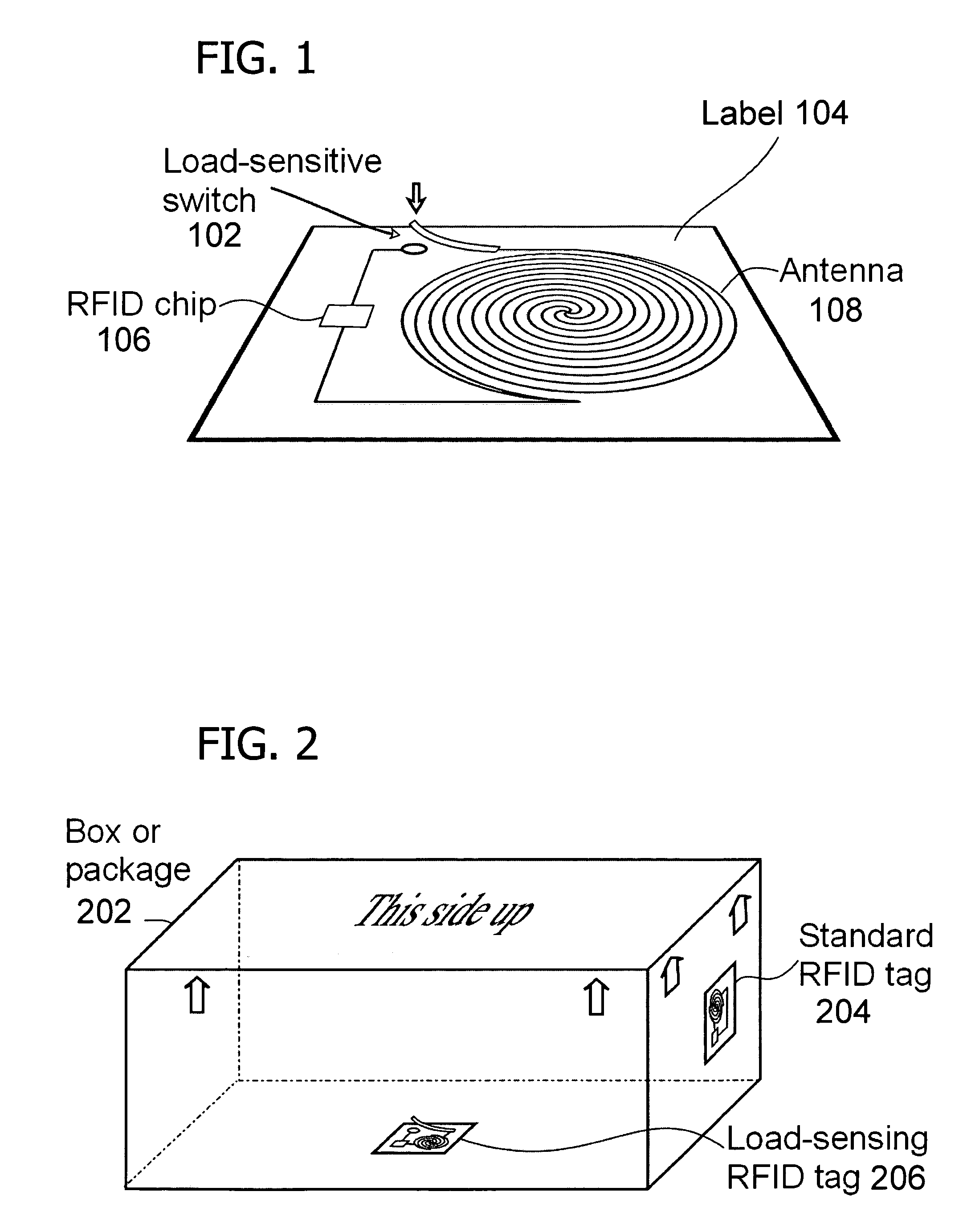
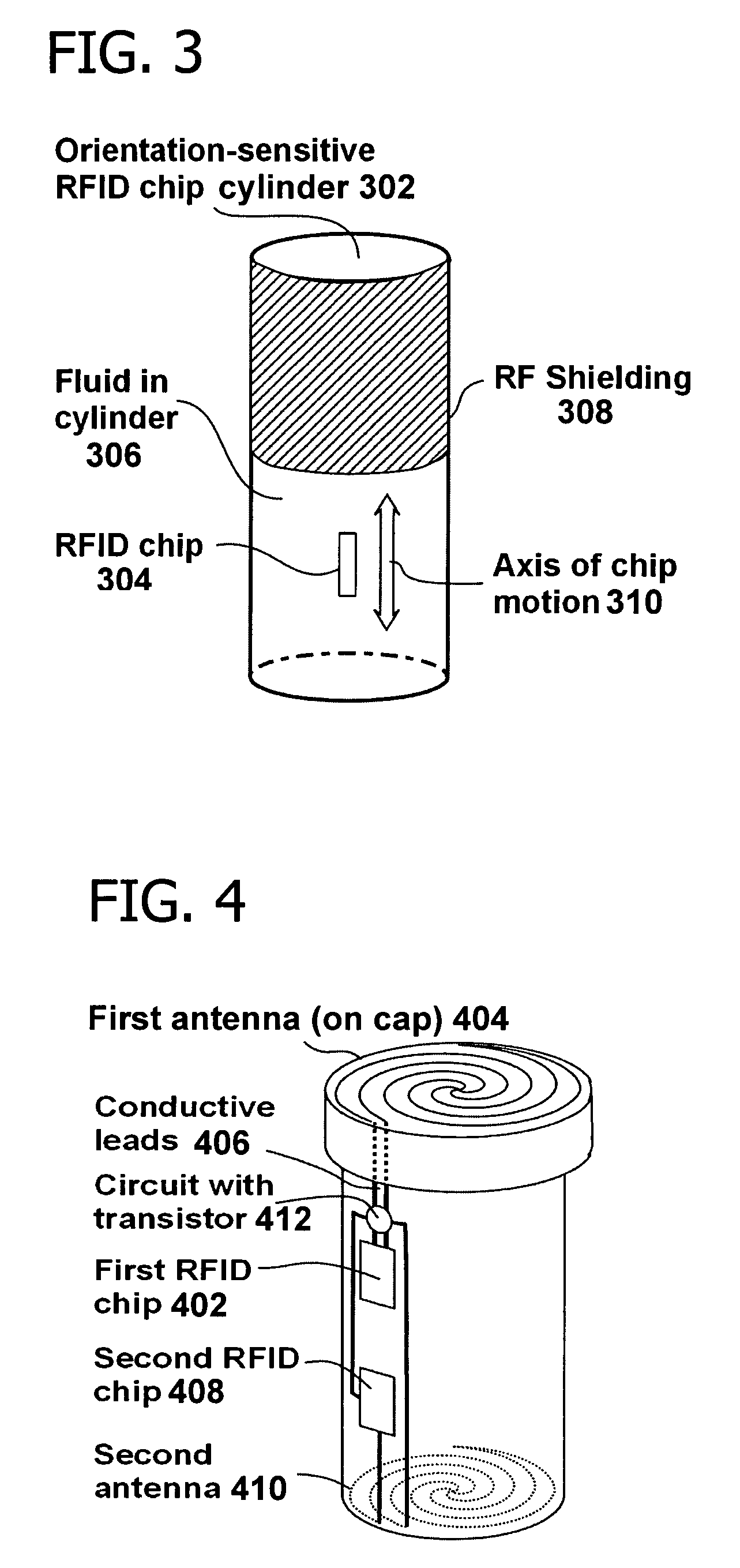
[0023]In one embodiment, the invention includes mechanically activating or deactivating a radio frequency identification (RFID) tag by load or orientation or user control. In particular, the invention includes a load-sensitive RFID circuit such as illustrated in FIG. 1 and FIG. 2, an orientation-sensitive RFID chip container such as illustrated in FIG. 3, a tamper-evident container with two RFID chips such as illustrated in FIG. 4, and an RFID tag with a removable antenna such as illustrated in FIG. 5. RFID chips may also be cooperatively associated with non-contacting removable antennas that provide energy via inductive coupling or resonance, as shown in FIG. 6.

Radio Frequency Identification (RFID)

[0024]RFID smart tag technology is known and understood by those skilled in the art, and a detailed explanation thereof is not necessary for purposes of describing the method and system according to the present invention. With RFID or other smart tag technology, a vendor may associate a u...


PUM


Abstract

Deactivating a data tag attached to packaging for user privacy or tamper-evident reasons. A data circuit stores identification information. A plurality of antennas is coupled to the data circuit. At least one antenna of the plurality of antennas is a removable antenna capable of wireless signal transmission at a first range such that removal of the antenna substantially prevents communication of the identification information via the removed antenna and permits communication of the identification information via another antenna of the plurality of antennas at a second range relatively smaller than the first range.

Description

FIELD OF THE INVENTION[0001]Embodiments of the invention generally relate to the field of radio frequency identification (RFID) tags. In particular, embodiments of the invention relate to a system and method for using one or more RFID tags for orientation, tamper-evidence, and user privacy.BACKGROUND OF THE INVENTION[0002]Radio frequency identification (RFID) technology refers to passive smart tags (miniature antenna-containing tags requiring no internal power supply) that may be embedded in or attached to a product or material to convey information that may be read by a scanner. Generally, conductive or passive smart tags include a data circuit and an antenna. In particular, smart tags include a semiconductor, a coiled, etched, or stamped antenna, a capacitor, and a substrate on which the components are mounted or embedded. A protective covering is typically used to encapsulate and seal the substrate.[0003]In general, RFID systems include readers and tags in which the tags generate...

Claims


Application Information

Patent Timeline
Patent Type & Authority Patents(United States)
IPC IPC(8): G08B13/14E05B73/00G06K19/073G06K19/077G08B13/24
CPCG06K19/0716G06K19/072G06K19/07767G06K19/07749G06K19/07345G08B13/24G06K17/00G08B13/08G08B13/00
Inventor LINDSAY, JEFFREY DEANVELAZQUEZ, HERIBERTO FLORESCHEN, FUNG-JOUWAGNER, ERIC FRANCIS
Owner BUFFALO PATENTS LLC
Why Eureka
Try Eureka