Autostereoscopic lenticular screen

a technology of lenticular screen and lenticular surface, which is applied in the direction of instruments, lighting and heating apparatus, optical elements, etc., can solve the problems of affecting the intelligibility of displayed images, and affecting the enjoyment of viewing displays

Inactive Publication Date: 2006-08-29
LEDOR LLC +1
View PDF8 Cites 73 Cited by
  • Summary
  • Abstract
  • Description
  • Claims
  • Application Information

AI Technical Summary

Benefits of technology

[0011]The present invention is an autostereoscopic lenticular screen. Such devices are generally known, wherein a lenticular screen is held in juxtaposition with a display surface. The lenticular screen is preferably formed of a glass substrate with lenticules disposed on one side thereof and a smooth surface on the other side thereof. In one aspect of the invention, a closed chamber is formed over the lenticules. In order to deactivate the refractive properties

Problems solved by technology

Such distractions are caused by the visibility of the lenticular screen structure itself.
These reflections interfere with the intelligibility of the displayed image as well as detract from the enjoyment of viewing the display.
An anti-reflection (AR) coating can be difficult to apply to a surface made up of miniature lenticules.
Another problem related to the unimpaired viewing and even the intelligibility of the display has to do with the need to switch between planar and stereo states.
It has been observed and understood that an application consisting of alpha numerics can become unintelligible when viewed through a lenticular screen because

Method used


Image

  • Autostereoscopic lenticular screen
  • Autostereoscopic lenticular screen
  • Autostereoscopic lenticular screen

Examples


Embodiment Construction

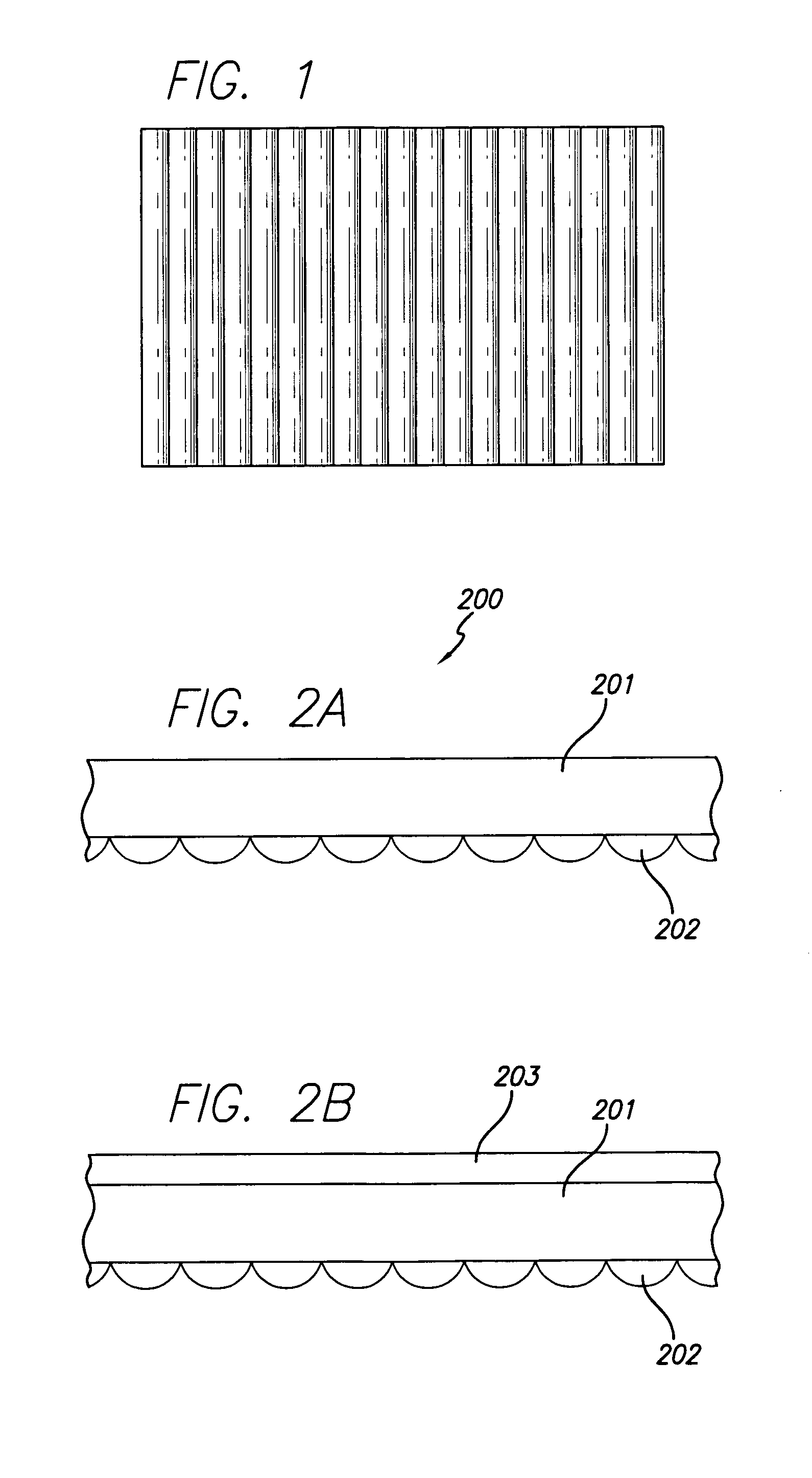
[0020]FIG. 2A shows a cross section of a lenticular screen 200 made up of lenticules 202, which are the topmost or sector-like surfaces of long cylinders, as deposited on substrate 201. Since our concern is for lenticular screens made to match the needs of electronic flat panel displays, we favor lenticules deposited on dimensionally stable glass; that is, on glass whose thermal expansion properties match that of the display screen so that the alignment of lenticule and pixel will remain constant. However, there is no loss of generality in our teaching if the substrate is some material other than glass, or if there is no substrate at all and the lenticular screen is a part of the substrate and made of one material.

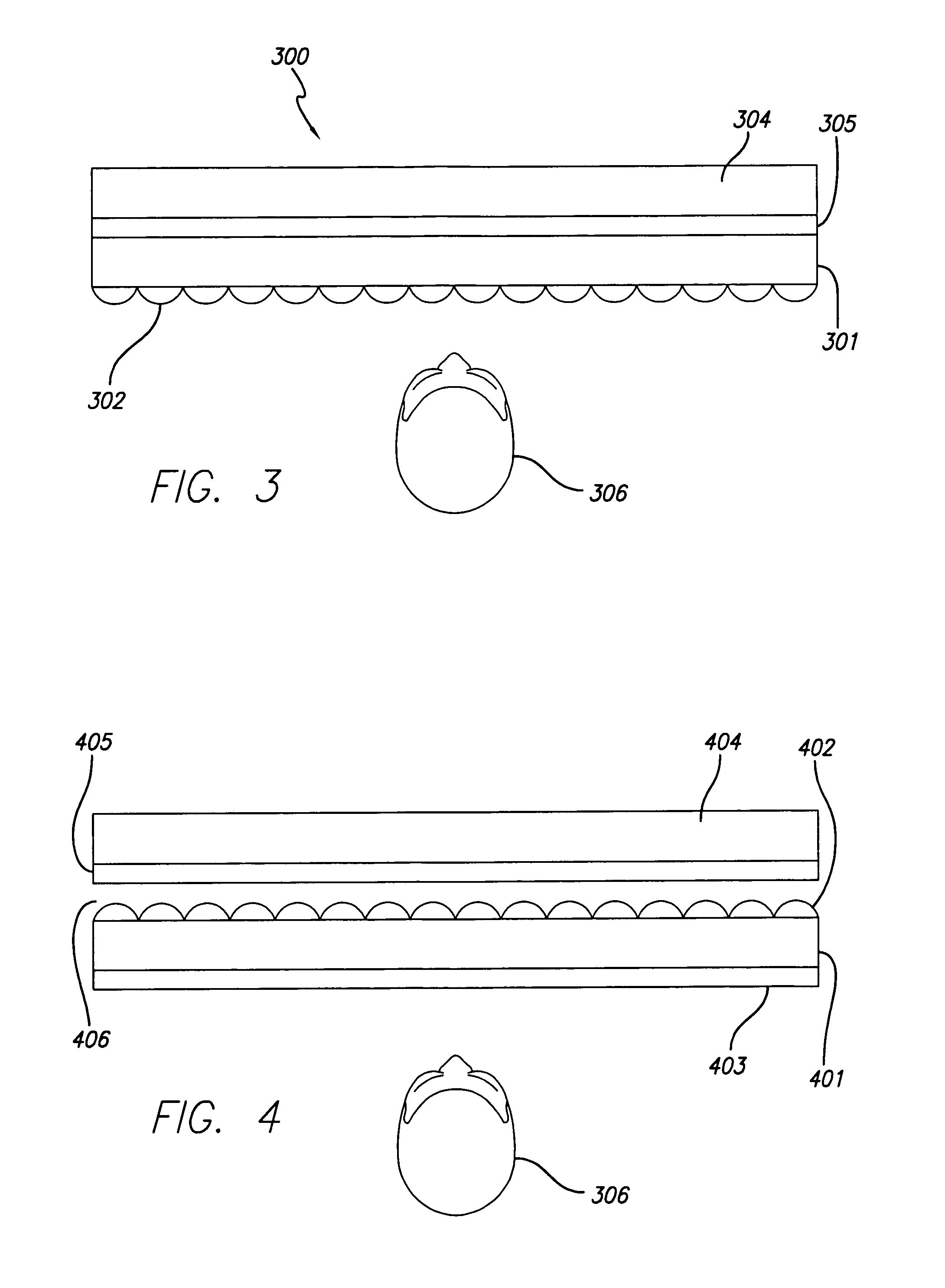
[0021]Our concern is with adding our screens to flat panel displays. We are constrained with regard to the thickness of a given panel cover-glass or faceplate. Each panel has a cover-glass that affects our ability to locate the lenticules with regard to the pixels themselv...


PUM


Abstract

An autostereoscopic lenticular screen has a lenticular screen held in juxtaposition with a display surface. The lenticular screen has lenticules disposed on one side thereof and a smooth surface on the other side thereof. In one aspect of the invention, a closed chamber is formed over the lenticules. In order to deactivate the refractive properties of the lenticular screen, and thereby view the display in a planar mode, an optically clear fluid, such as a fluoropolymer, is introduced into at least a portion of the closed chamber. In order to activate the refractive properties of the lenticular screen, and thereby view the display in a stereoscopic mode, the optically clear fluid is removed from the closed chamber. In a particularly preferred arrangement, the lenticular screen is oriented such that the lenticules face inwardly toward the display screen, and the smooth surface of the lenticular screen is coated with an antireflective material.

Description

BACKGROUND[0001]Lenticular screens have long been a means to provide the user with an autostereoscopic display allowing each eye to see a different perspective. The idea of using a corduroy-like lenticular screen and an interdigitated stereo pair was first enunciated in 1915 by Hess in U.S. Pat. No. 1,128,979, and there has been much art disclosed in the field since Hess.[0002]Indeed, the idea of using lenticular screens with inward facing lenticules, which we employ in this disclosure, has been applied for years in the manufacture of rear projection television sets. It is the manner in which we use this configuration and improve upon it that leads to great improvements in image quality as will be described below.[0003]When viewing a lenticular autostereoscopic display, the user does not wish to be aware of the structure or the presence of the screen. The user is concerned with seeing the image and does not wish to be subjected to any distraction. Such distractions are caused by the...

Claims


Application Information

Patent Timeline
IPC IPC(8): G02B27/22H04N13/04G02B30/27H04N13/00
CPCG02B27/2214H04N13/0404H04N2213/001H04N13/305G02B30/27
Inventor LIPTON, LENNYMCKEE, WILLIAMHALNON, JEFFREY JAMES
Owner LEDOR LLC
Why Eureka
Try Eureka