
Balance ring

a ring and balance technology, applied in the field of disk drives, can solve problems such as id imperfections, substrates may encounter balancing problems, and disk substrate imperfections may be particularly problemati

Inactive Publication Date: 2006-08-29
WD MEDIA
View PDF27 Cites 71 Cited by
  • Summary
  • Abstract
  • Description
  • Claims
  • Application Information

AI Technical Summary

Benefits of technology

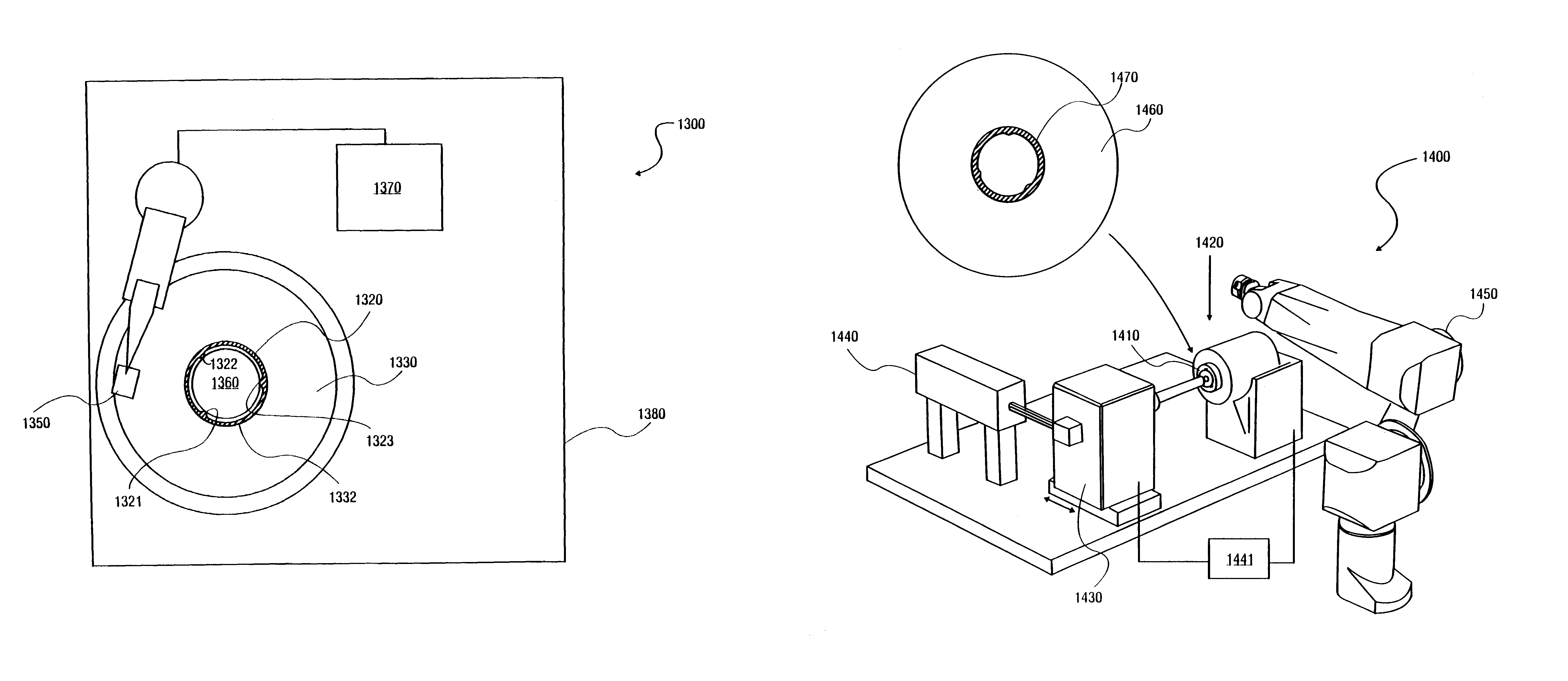
"The present invention is about an apparatus and method for balancing a disk. The apparatus includes a circular band with clamps that can be attached to the disk. The band has protuberances on its inner surface. The method involves attaching the band to the disk and then trimming the protuberances to create a new rotational center for the disk and band that aligns with the mass center of the disk and band. The technical effect of this invention is to provide a way to balance disks quickly and accurately using a simple apparatus and method."

Problems solved by technology

Also, the scribe lines have a tendency to overlap resulting in imperfections to the disk substrate.
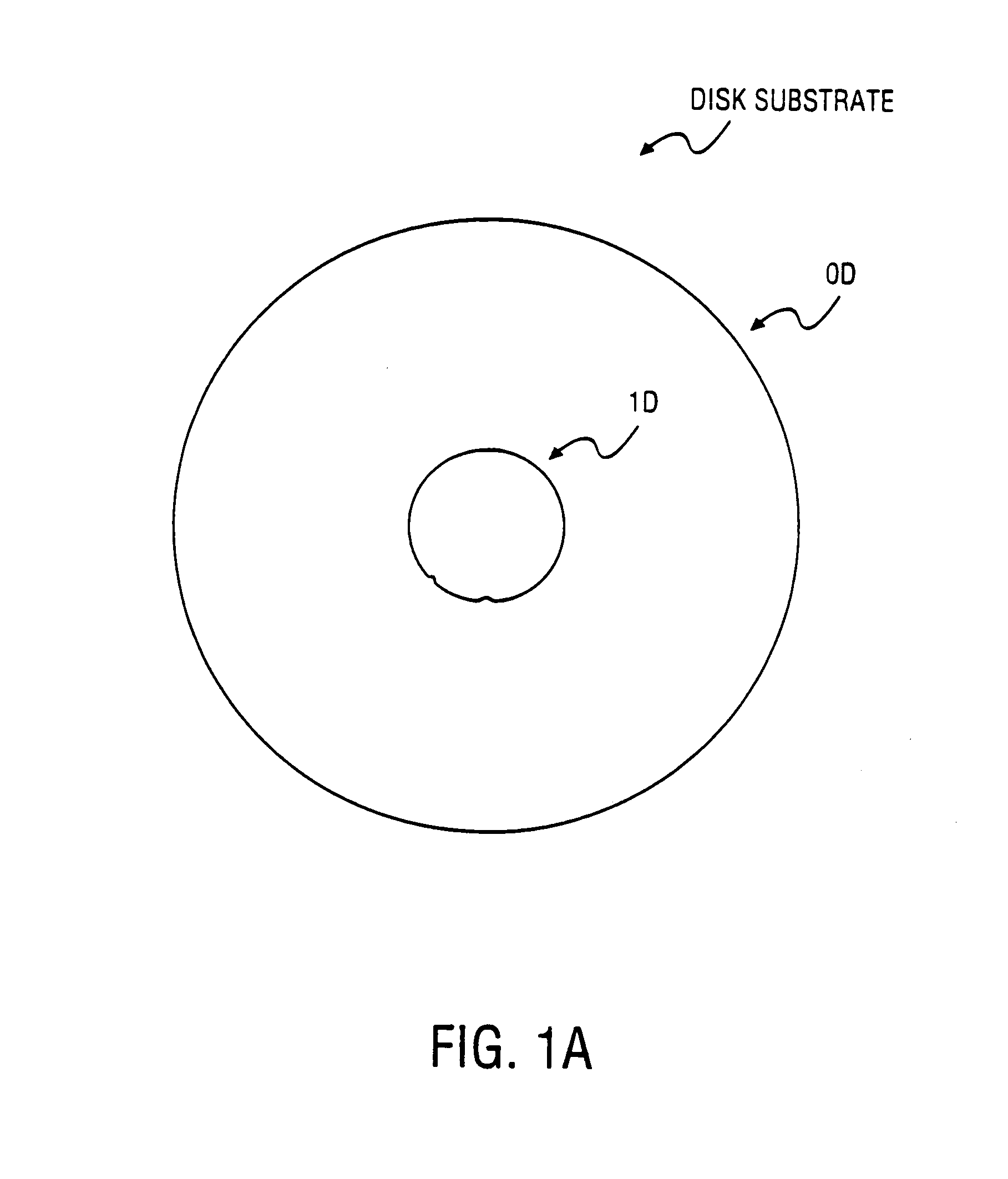
The ID imperfections may be especially problematic because the ID is mounted onto the spindle of the disk drive.
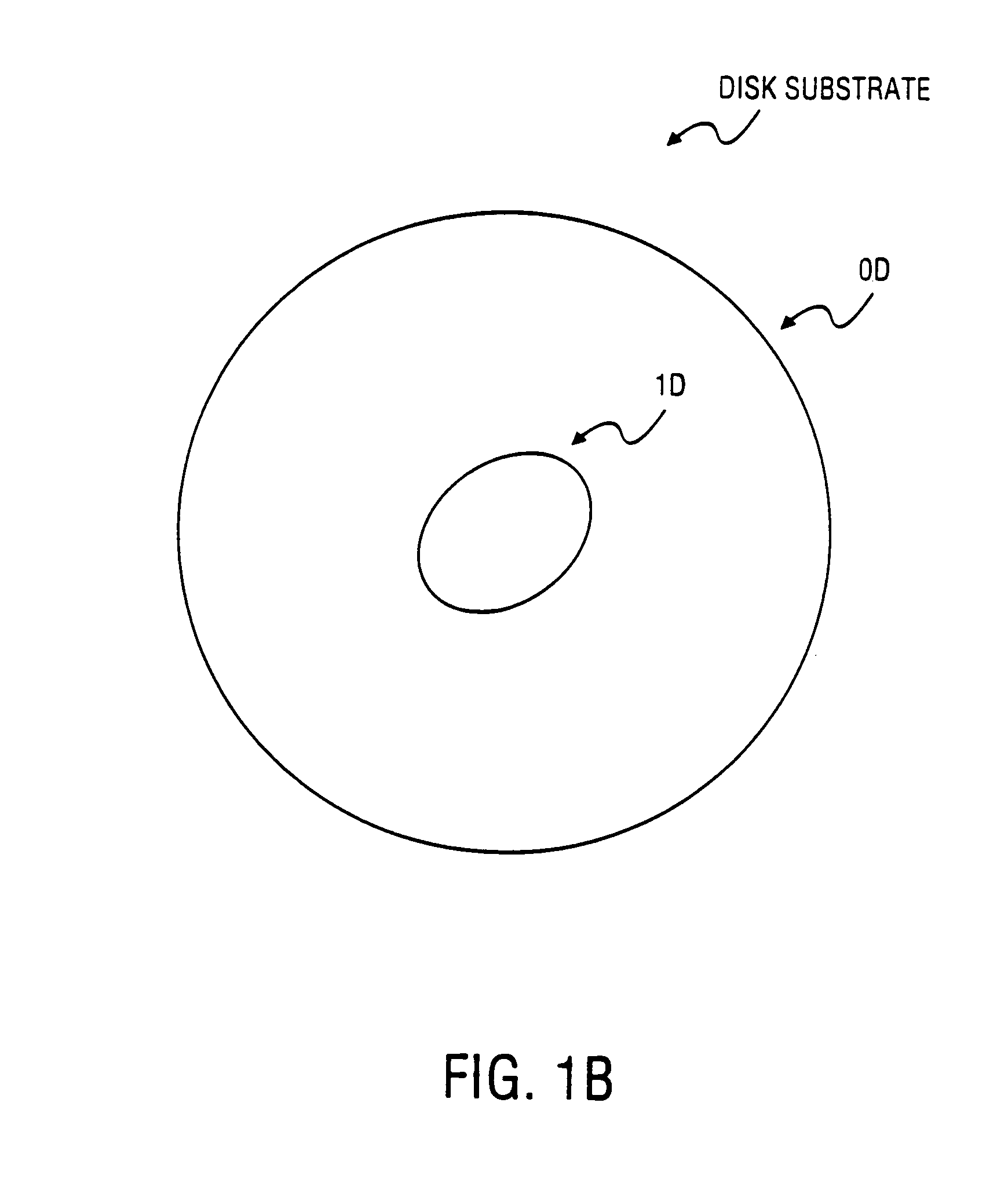
The mass center may be at point A, while the rotational center (substantially the ID geometric center at which the disk rotates when mounted) may be at point B. A disk having this type of substrate may encounter balancing problems when rotated on the spindle of a disk drive system.
A high rotational speed of an unbalanced disk may lead to poor performance or disk failure.
Another problem of disk substrate scribing results from the ID having a greater size than the drive spindle in order to fit properly over the disk drive spindle.
However, because of manufacturing limitations, such precision may not be practical.
Although disks that are not mass balanced during manufacturing could be corrected in post-production steps, current methods to correct disk imbalance may be costly and time consuming.
Additionally, in multiple disk systems, mass balancing may be even more complex and costly compared to single disk systems.

Method used


Image

  • Balance ring
  • Balance ring
  • Balance ring

Examples


Embodiment Construction

[0033]In the following description, numerous specific details are set forth such as examples of specific materials or components in order to provide a thorough understanding of the present invention. It will be apparent, however, to one skilled in the art that these specific details need not be employed to practice the invention. In other instances, well known components or methods have not been described in detail in order to avoid unnecessarily obscuring the present invention.

[0034]It should be noted that the apparatus and methods discussed herein may be used with various types of disks. In one embodiment, for example, the apparatus and methods discussed herein may be used with a magnetic recording disk. Alternatively, the apparatus and methods discussed herein may be used with other types of digital recording disks, for examples, a compact disc (CD) and a digital video disk (DVD).

[0035]In one embodiment, the apparatus and method described herein may be implemented with a glass su...


PUM

PropertyMeasurementUnit
anglesaaaaaaaaaa
mass centeraaaaaaaaaa
massaaaaaaaaaa

Abstract

An apparatus and method for balancing a disk are described. A balance ring may be a circular band for placement along the inner diameter of a disk. On the outer diameter of the balance ring, one or more clamp structures may extend outward to attach the balance ring to the inner diameter of a disk. The inner diameter of the balance ring may have a number of protuberances that, when trimmed, establish a new rotational center of the disk / balance ring coincident with the mass center. The disk and balancing ring may be mounted on a disk balancing system to determine a mass center and trim the protuberances, accordingly, to establish adjust the rotational center of the disk / balance ring to be coincident with the mass center. The protuberances may be trimmed using, for example, laser energy.

Description

[0001]This application is a divisional of Application Ser. No. 10 / 712,548 filed Nov. 12, 2003 now U.S. Pat. No. 6,778,353, which is a divisional of Application Ser. No. 09 / 916,144 filed Jul. 25, 2001 now abandoned.FIELD OF THE INVENTION[0002]This invention relates to the field of disk drives and, more specifically, to mass balancing of disks for use in disk drive systems.BACKGROUND OF THE INVENTION[0003]A disk drive system typically consists of one or more magnetic recording disks and control mechanisms for storing data within approximately circular tracks on a disk. A disk is composed of a substrate and one or more layers deposited on the substrate. In most systems, an aluminum substrate is used. However, alternative substrate materials such as glass have various performance benefits such that it may be desirable to use a glass substrate.[0004]To produce a substrate from a blank sheet of a brittle material such as glass, the material may be scribed to generate a substrate having an...

Claims


Application Information

Patent Timeline
Patent Type & Authority Patents(United States)
IPC IPC(8): G11B17/028
CPCG11B23/0028
Inventor HARPER, BRUCE M.
Owner WD MEDIA
Learn More