Method of determining by numerical simulation the restoration conditions, by the fluids of a reservoir, of a complex well damaged by drilling operations

a technology of fluids and reservoirs, applied in the field of numerical simulation of the restoration conditions, by the fluids of a reservoir, of a complex well damaged by drilling operations, can solve the problems that laboratory surveys are often insufficient by themselves to realistically model the production

Inactive Publication Date: 2006-08-29
INST FR DU PETROLE
View PDF0 Cites 26 Cited by
  • Summary
  • Abstract
  • Description
  • Claims
  • Application Information

AI Technical Summary

Benefits of technology

[0016]The simulation performed according to the method allows reservoir engineers to better predict the best development scheme for the reservoir while avoiding drawbacks such as

Problems solved by technology

However, the surveys carried out in the laboratory are often insufficient by themselves to realistically model the production condi

Method used


Image

  • Method of determining by numerical simulation the restoration conditions, by the fluids of a reservoir, of a complex well damaged by drilling operations
  • Method of determining by numerical simulation the restoration conditions, by the fluids of a reservoir, of a complex well damaged by drilling operations
  • Method of determining by numerical simulation the restoration conditions, by the fluids of a reservoir, of a complex well damaged by drilling operations

Examples


example 1

Clearing in the Presence of the Internal Cake Alone

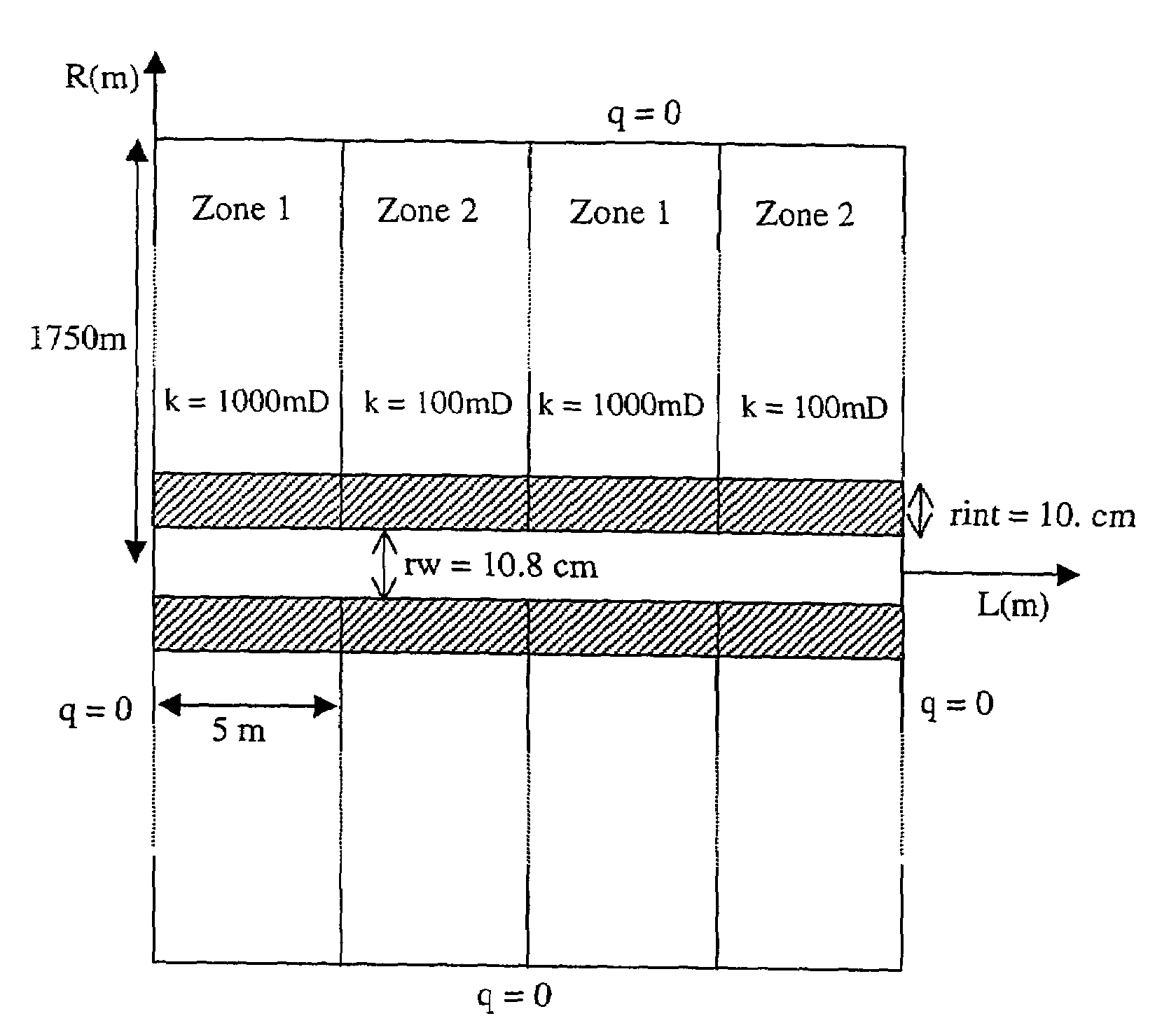
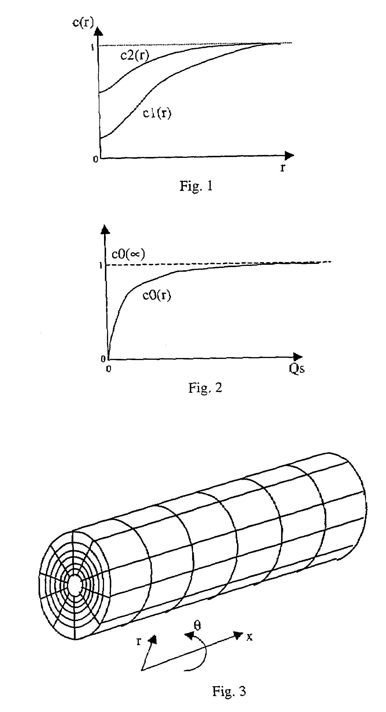
[0069]A 20-m long part of a horizontal well running through 4 zones is considered which “alternately representative of two different heterogeneity types (FIG. 6). The permeabilities k of the corresponding media, initially without damage, are 1000 and 100 mD. The length of each medium crossed is 5 m. The values of the permeability in the grid cells where the internal cake due to the damage has formed are entered manually into the data set. The curves, by zones, of the multiplying coefficient of the damage permeability as a function of the distance to the wall of the well c1(r) are given in FIG. 7. The restored permeability curves c2(r) are shown in FIG. 8. These curves are discontinuous because the data supplied by the laboratory measurements only concern some points. The larger the number of points, the better the laboratory curve is represented. The permeability variation during cleaning as a function of the amount of fluid flowing...

example 2

Presence of a Non-Uniform External Cake Along the Horizontal Well

[0080]The same well geometry is considered as in the previous example. In this example, the reservoir is homogeneous with a 1000-mD permeability in the porous medium. The external cake has no homogeneous presence along the well. In some places, there is no external cake, and in the places where the external cake is present, it has a 1-mD permeability kext and a 4-mm thickness rext as in the previous example. The distribution of the presence of the external cake is given in FIG. 13. The pressure difference required for removing the external cake is still set at 0.5 bar.

[0081]Two types of boundary conditions are used in the simulations. For the first case, a 318.2-bar pressure is applied at the well bottom, i.e. a 1.8-bar pressure difference between the reservoir and the well. For the second case, several consecutive pressure stages are applied to reach a total 1.8-bar pressure drop (Table 2).

[0082]FIGS. 14 and 15 show t...


PUM


Abstract

The method essentially comprises acquiring initial data obtained by laboratory measurements of the values, according to the initial permeability of the formations surrounding the well, of the thickness of the cakes and of the damaged permeability and restored permeability values of this zone, as a function of the distance to the wall of the well. Then the damaged zone is discretized by a 3D cylindrical grid pattern forming blocks of small radial thickness in relation to the diameter of the well, and the diffusivity equation, modelling the flow of the fluids through the cakes, is solved in this grid pattern by taking account of the measured initial data. Finally, the evolution of the permeability is modelled as a function of the flow rates of fluids flowing through the cakes, so as to deduce therefrom the optimum conditions to be applied for producing the well.

Description

BACKGROUND OF THE INVENTION[0001]1. Field of the Invention[0002]The present invention relates to a method of determining by numerical simulation the optimum conditions to be applied in a horizontal (or complex) well drilled through an underground reservoir, so as to progressively eliminate (restore), by flushing by means of the production fluids from the reservoir, deposits or cakes formed in at least a peripheral zone of the well, as a result of drilling and completion operations.[0003]It is well-known to the man skilled in the art to distinguish between the cakes referred to as internal cakes, formed by mud invasion of the rock pores, and the cakes referred to as external cakes, consisting of a mud coat on the external wall of the well.[0004]2. Description of the Prior Art[0005]It is well-known in the art to distinguish between the cakes referred to as internal cakes, formed by mud invasion of the rock pores, and the cakes referred to as external cakes, consisting of a mud coat on...

Claims


Application Information

Patent Timeline
IPC IPC(8): G06G7/48E21B49/00
CPCE21B37/00E21B49/00E21B43/12E21B43/00
Inventor DING, YU DIDIERLONGERON, DANIELRENARD, GERARDAUDIBERT HAYET, ANNIE
Owner INST FR DU PETROLE
Why Eureka
Try Eureka