Vision correction system, method and graphical user interface for implementation on electronic devices having a graphical display

a technology of graphical display and vision correction system, which is applied in the direction of static indicating device, image enhancement, instruments, etc., can solve the problems of limited success, limited ability of software to manipulate display images, and current techniques that have so far failed to provide a reliable solution for electronic device users with reduced visual acuity, etc., to achieve better prediction, more accurate display correction settings, and greater cross section of the population

Active Publication Date: 2017-03-02
EVOLUTION OPTIKS
View PDF3 Cites 95 Cited by
  • Summary
  • Abstract
  • Description
  • Claims
  • Application Information

AI Technical Summary

Benefits of technology

[0033]In some embodiments, the system may be configured to invoke a server-based calibration process that not only allows for the centralized management of a user's calibration parameters, which may facilitate, enhance or enable various user-centric account or profile features such as calibration portability between user, public or shared devices, but also allow for the accumulation, tracking and analysis of calibration parameters from multiple users or subscribers. The latter may be used to better predict and deliver more accurate display correction settings to each user based on similarities observed between reported user conditions and selected settings, thus further enabling the provision of visual settings that allow a greater cross section of the population to use their device without the need for corrective lenses.

Problems solved by technology

These techniques focus on the limited ability of software to manipulate display images through conventional image manipulation, with limited success.
In any event, current techniques have thus far failed to provide a reliable solution for electronic device users having reduced visual acuity and who may wish to interact with their device's graphical display without the use of corrective eyewear, for example.

Method used


Image

  • Vision correction system, method and graphical user interface for implementation on electronic devices having a graphical display
  • Vision correction system, method and graphical user interface for implementation on electronic devices having a graphical display
  • Vision correction system, method and graphical user interface for implementation on electronic devices having a graphical display

Examples


Embodiment Construction

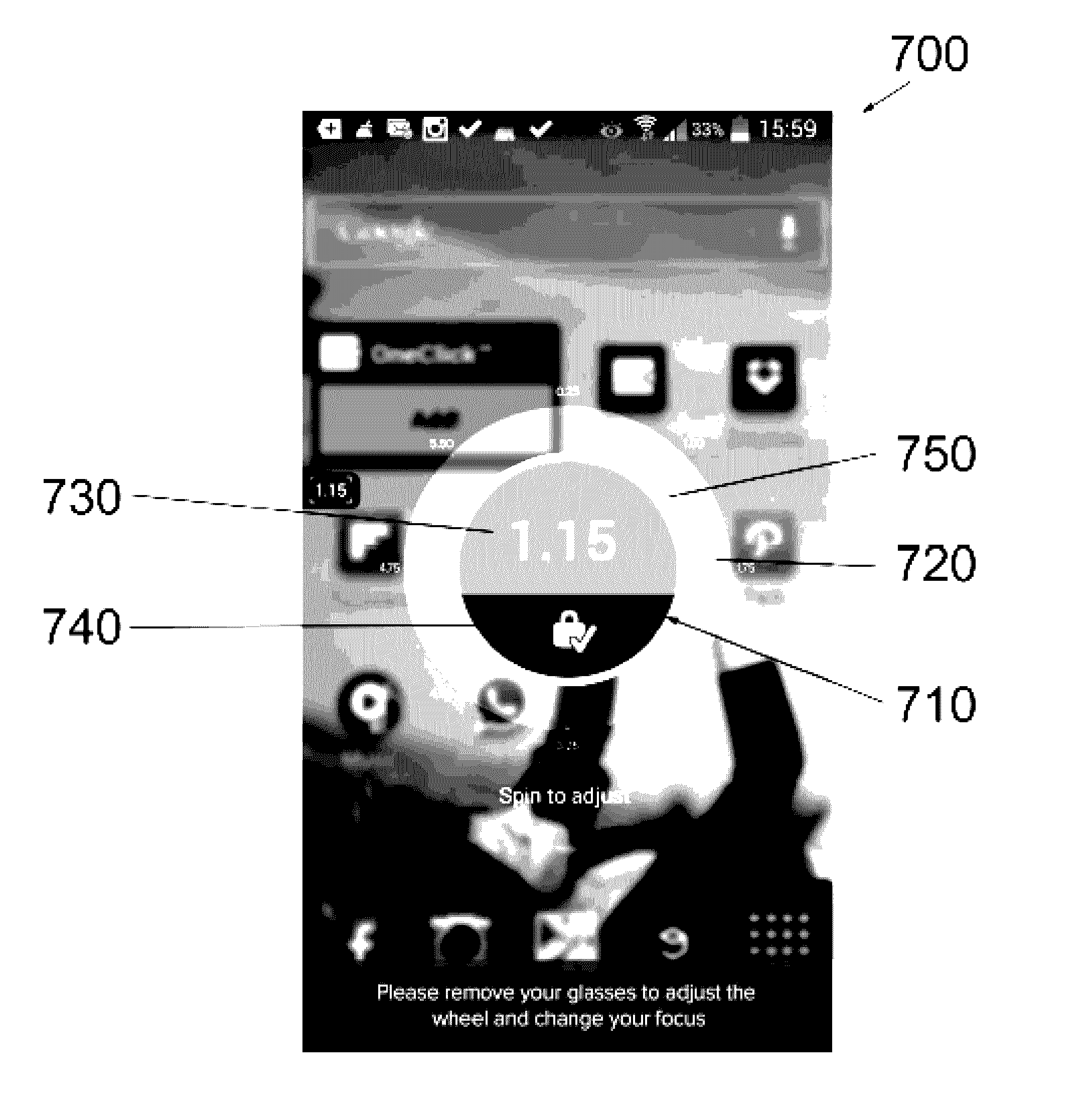
[0051]The systems and methods described herein provide, in accordance with different embodiments, different examples an electronic device having an adjustable graphical display, and a vision correction system, method and graphical user interface therefor.

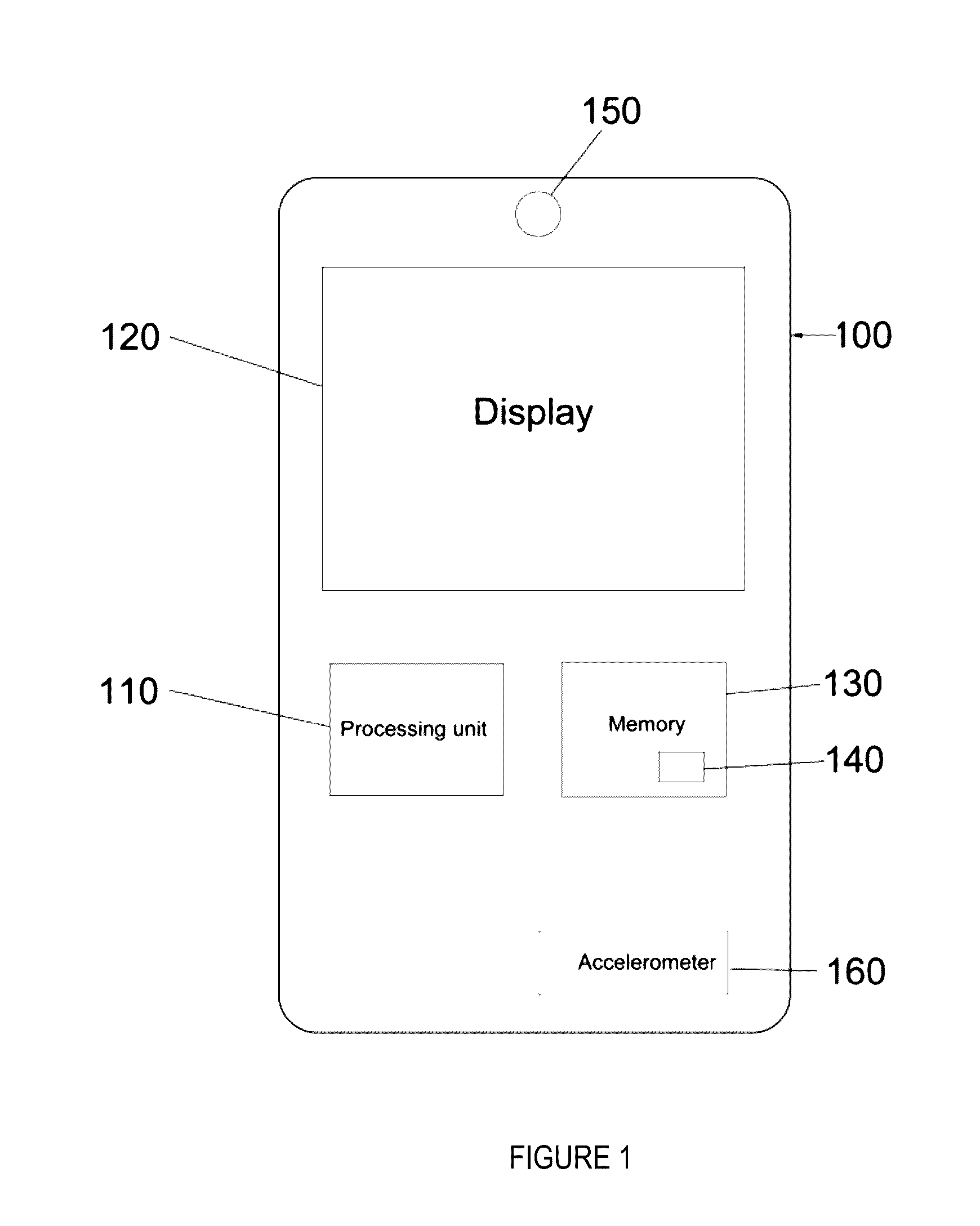
[0052]FIG. 1 illustrates an electronic device 100 according to an embodiment. Electronic device 100, while depicted as a cellular telephone, is not limited to a cellular telephone. Other devices capable of implementing the disclosed embodiments include, for example, smartphones, tablets, e-readers, watches, televisions, GPS devices, laptops, and desktop computers. Likewise, an onboard vehicle entertainment or control module having a digital screen output or the like may also be considered, as can a digital watch, such as smart watch or the like. Any electronic device capable of performing the present embodiments is considered to be within the scope of electronic device 100.

[0053]Electronic device 100 includes a processing unit 110, ...


PUM


Abstract

Described are various embodiments of an electronic device having an adjustable graphical display, and a vision correction system, method and graphical user interface therefor.

Description

CROSS REFERENCE TO RELATED APPLICATION[0001]This application claims the benefit of priority to Canadian Patent Application No. 2,901,477, which was filed Aug. 25, 2015, and is incorporated herein by reference in its entirety and for all purposes.FIELD OF THE DISCLOSURE[0002]The present disclosure relates to electronic devices having a graphical display, and in particular, to a vision correction system, method and graphical user interface for implementation on such electronic devices.BACKGROUND[0003]The operating systems of current electronic devices having graphical displays offer certain “Accessibility” features built into the software of the device to attempt to provide users with reduced vision the ability to read and view content on the electronic device. Specifically, current accessibility options include the ability to invert images, increase the image size, adjust brightness and contrast settings, bold text, view the device display only in grey, and for those with legal blind...

Claims


Application Information

Patent Timeline
Patent Type & Authority Applications(United States)
IPC IPC(8): G06F3/0484G02B27/02G09G5/30G06F3/0482G06F3/14
CPCG06F3/04847G06F3/0482G06F3/14G09G5/30G02B27/02G09G2320/0606H04L67/12G09G2354/00G09G2370/02G09G2340/14G06T1/0007G06T5/00G09G2320/0693G09G2320/0626H04L67/306H04L67/125H04L67/04H04L67/10G06F3/147G09G5/003G09G2320/0261G09G2380/08G02B30/27
Inventor HOUGH, NATHAN L.HOUGH, CHRISTOPHER J. S.SHARPE, JENNIFER K.HOUGH, RYAN M.VIGEANT, LUKE A.
Owner EVOLUTION OPTIKS
Why Eureka
Try Eureka