
Eureka
For R&D, Eureka makes reading and utilizing patents & technical documents easy.
Eureka AIR
Designed for self-driven R&D workflows. Generate viable solutions, solve complex R&D challenges, empower your innovation with AI.

Eureka Materials
Designed for material experts only. Revolutionize your material R&D, from search, analyze, to developing new materials.

TechResearch
Generate reliable direction feasibility study reports for your R&D in just a few steps.

TechSeek
Discover and master advanced knowledge NOW. Basics, ideas, possibilities, all at once.

TechMind
As an expert in R&D Theories, TechMind can generates customized viable solutions instantly.

TechRisk
Analyze your overall solution with one click, know your potential R&D risks in advance.

TechMonitor
Get weekly tech updates, stay abreast of the latest tech innovations and key insights.
Method for allowing simple interoperation between backend database systems
- Summary
- Abstract
- Description
- Claims
- Application Information
AI Technical Summary
Problems solved by technology
Method used
Image

Examples
Embodiment Construction
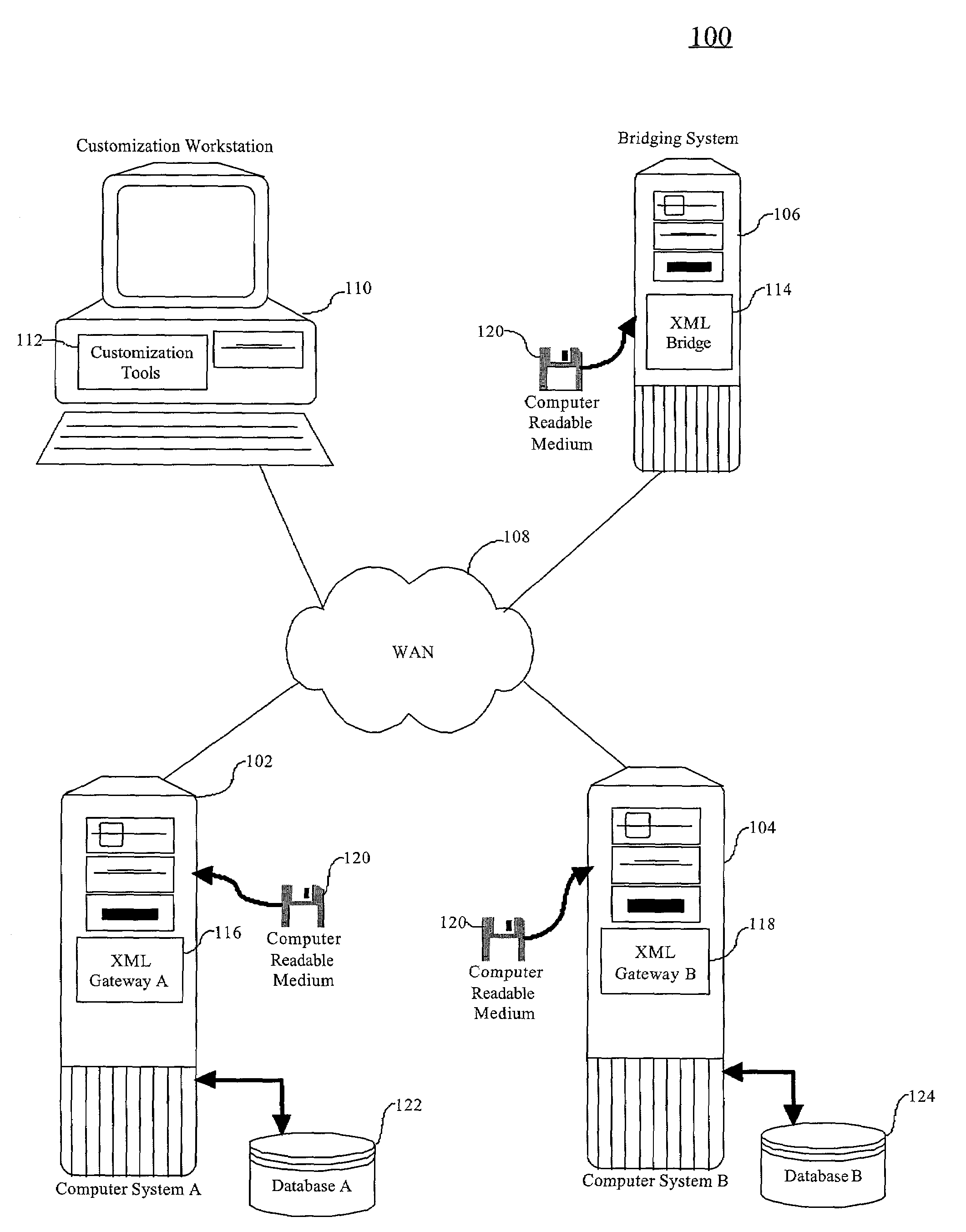
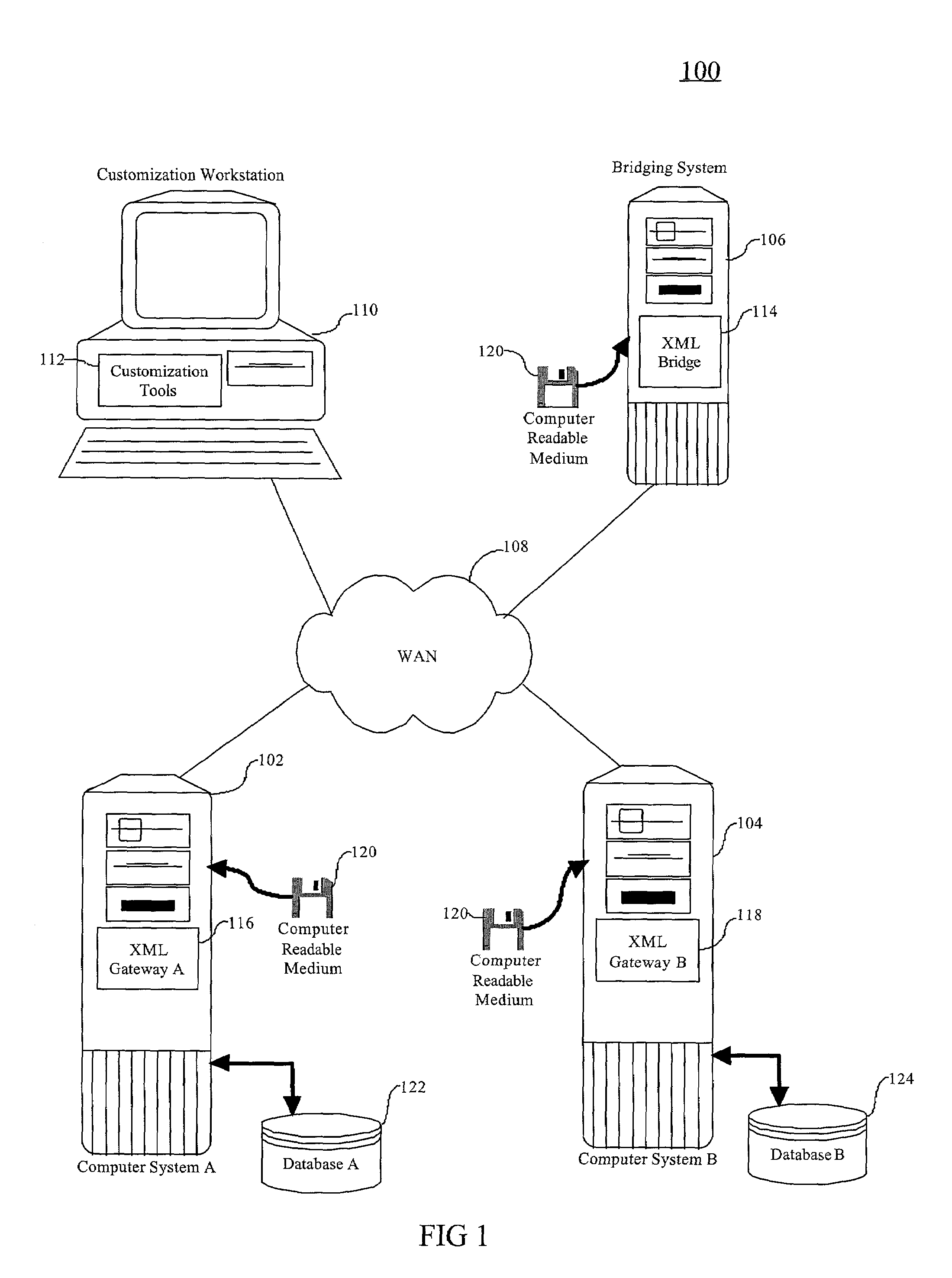
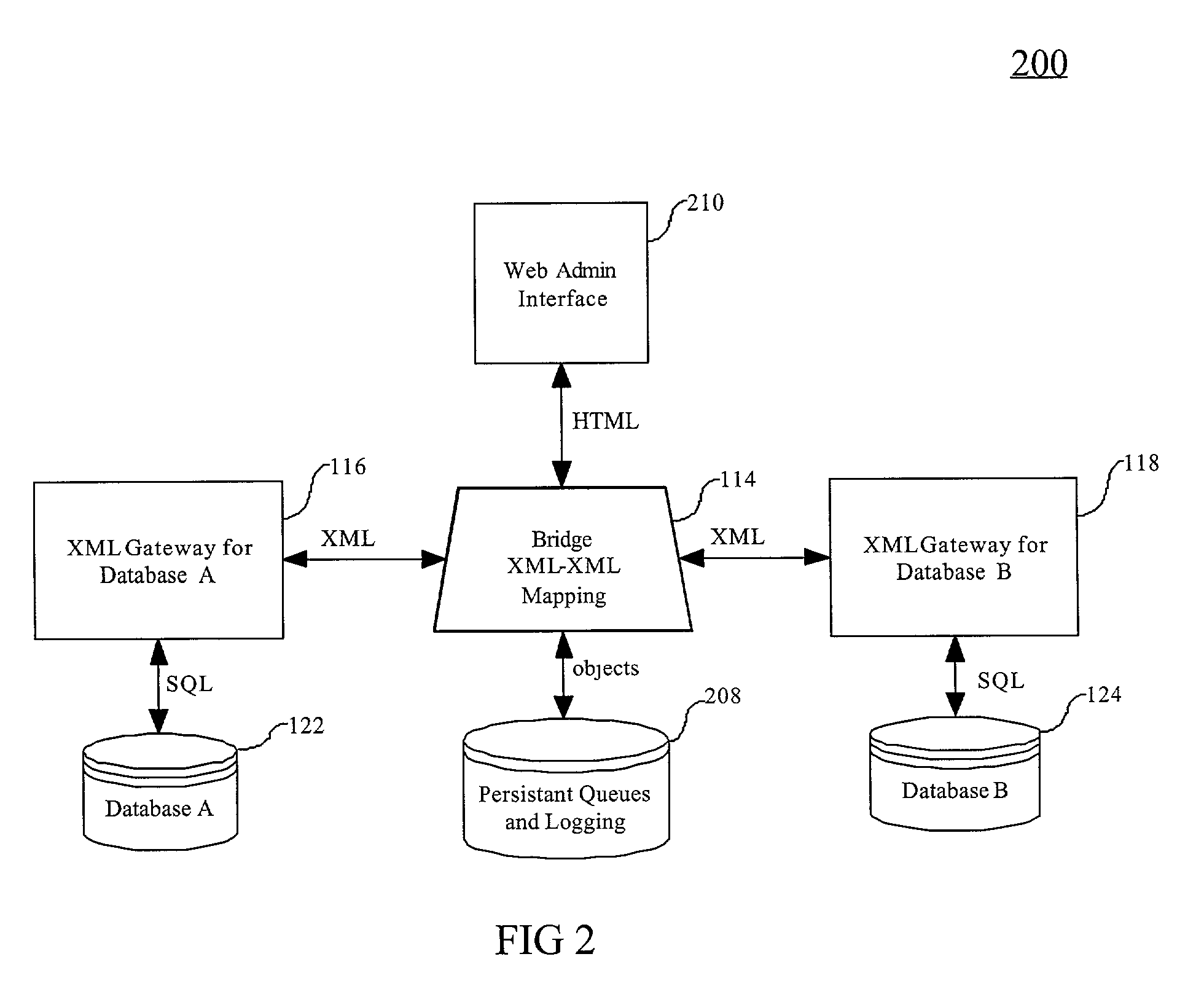
[0013]The present invention, according to a preferred embodiment, overcomes problems with the prior art by implementing a database independent Bridge responsible for managing ticket queues containing problem tickets, for example, being shipped from one problem management system to another via a pair of database specific Gateways. It also uses XML as the language in which data is passed from one component to another making it easy to plug different problem management systems by simply plugging in their data dictionary in the form of a document type definition (DTD).
[0014]A preferred embodiment achieves this level of autonomous interoperation using common web standards such as HTTP, XML, HTML, and relational query language SQL.
[0015]FIGS. 1 and 2 illustrate an exemplary bridging system according to a preferred embodiment of the present invention. The bridging system 100 includes a computer system A 102, having an XML gateway 116 and communicatively coupled to a database system A 122. ...
PUM
 Abstract
Description
Claims
Application Information
 - R&D Engineer
- R&D Manager
- IP Professional
- Industry Leading Data Capabilities
- Powerful AI technology
- Patent DNA Extraction
Browse by: Latest US Patents, China's latest patents, Technical Efficacy Thesaurus, Application Domain, Technology Topic, Popular Technical Reports.
© 2024 PatSnap. All rights reserved.Legal|Privacy policy|Modern Slavery Act Transparency Statement|Sitemap|About US| Contact US: help@patsnap.com