Device for a foot

Inactive Publication Date: 2006-09-05
ROOT ANDREW CARL
View PDF21 Cites 4 Cited by
  • Summary
  • Abstract
  • Description
  • Claims
  • Application Information

AI Technical Summary

Benefits of technology

[0016]The planar member may be hingedly connected to one or more further planar members to allow separate forefoot and rear foot movement and first ray movement of the foot to be detected.
[0017]The device according to the invention is advantageous primarily in that it facilitates more accurate taking of three dimensional impressions of feet, which is currently carried out manually holding the foot whilst the plaster hardens to form the cast. The accuracy of alignment may be within a single degree or better. The de

Problems solved by technology

A major problem with conventional methods of making casts and impressions of feet is their inherent lack of reproducibi

Method used


Image

  • Device for a foot
  • Device for a foot
  • Device for a foot

Examples


Embodiment Construction

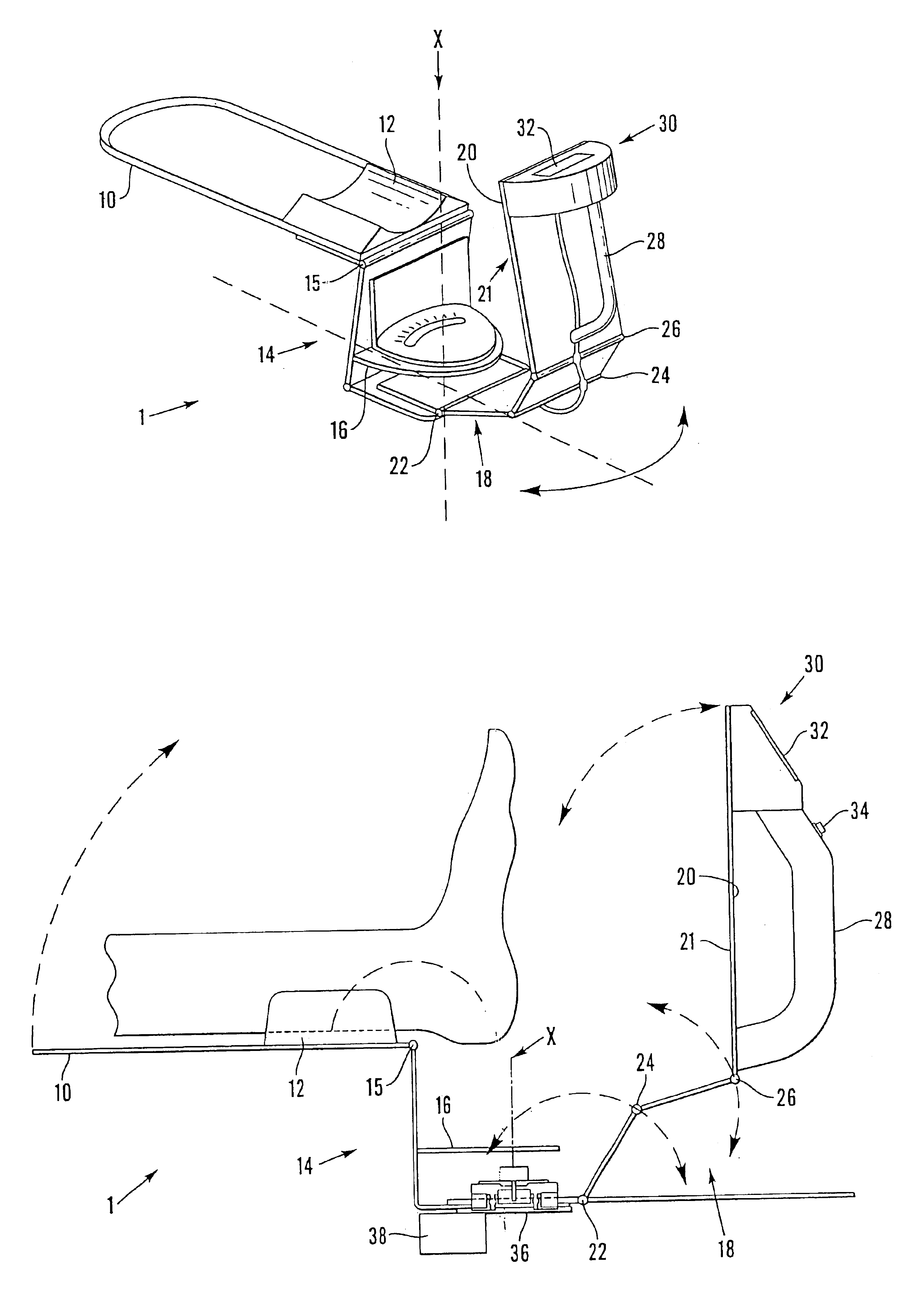
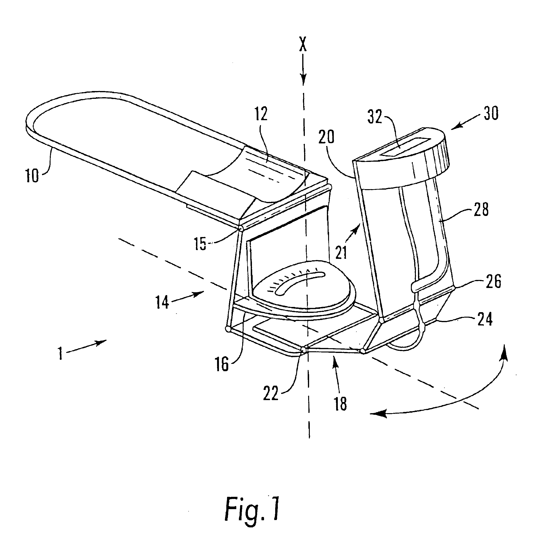
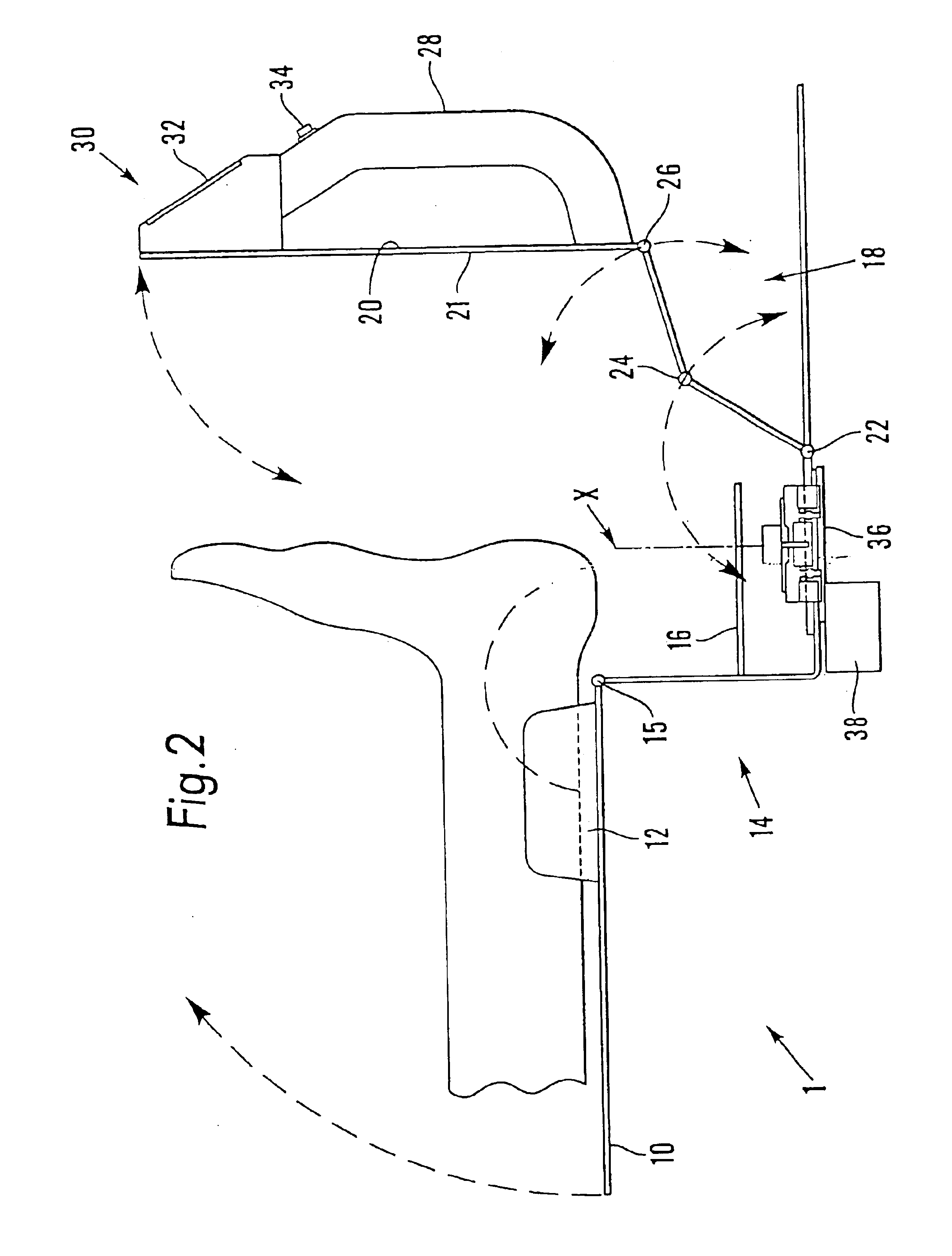
[0034]Referring first to FIGS. 1 and 2, a device according to the invention is generally designated at 1. The device 1 comprises a leg rest 10 which, in use, is placed on the edge of the chair or couch on which a patient sits or lies, the patient's lower leg being supported by the rest 10 with the ankle and foot projecting beyond it. The front edge of the rest 10 is provided with a soft insert 12, which acts as a lower leg rest for the patient's comfort.

[0035]The rest 10 has a downwardly directed front portion 14 on which a removable tray 16 is received. The front portion 14 is hingedly connected at 15 to the rest 10, to allow the device to be folded for ease of transport.

[0036]An articulated platform 18 is pivotally mounted at a lower level on the front portion 14 of the rest 10. Hence, the platform 18 can be rotated about a vertical axis X. The platform 18 carries a planar member in the form of a rigid plate 20 having a planar surface 21 which, in use, is brought into contact with...


PUM


Abstract

A device and method is provided whereby application is made to at least part of the sole of a suitably positioned foot for inverting or everting the foot. The device (1) (FIGS. 1 and 2) comprises a member or plate (20) having a planar surface (21) for pressure application to the sole by a handle (28) and in one arrangement is hingedly mounted (22, 24, 26) about horizontal axes from a leg rest (10) which lies in use on a seat or couch for the patient. This enables the surface (21) to be brought against the sole and also tilted for required contact with the latter. The plate (20) is also shown mounted for angular movement about a vertical axis X for additional tilting of the surface (21). An electronic unit (30) on the plate (20) has an LCD display (32) for showing angles of tilt. With the surface (21) in appropriate contact the sole can be manually palpated or manipulated e.g. for contact of the surface (21) with metatarsal joints or points, and/or the subtalar joint palpated for the neutral condition etc. The required position of the surface (21) is maintained while moulding material such as plaster of Paris (e.g. as a bandage) is applied to the sole and foot and allowed to set in providing a mould for use in the manufacture of orthoses. Alternatively, the plate may be simply hand held for similar operation. The planar surface may have buttons each for initial contact with a metatarsal point for indicator lamp operation when the metatarsal point lifts away. The handle may operate strain gauge means of the electronic unit to indicate application pressure at the LCD display.

Description

[0001]The present application is a continuation application from U.S. patent application Ser. No. 09 / 918,582 filed on 31 Jul. 2001 now U.S. Pat. No. 6,782,630.BACKGROUND OF THE INVENTION[0002]This invention relates to a device for a foot.[0003]Foot orthotics are an essential part of conservative orthopaedic treatment for correction of biomechanical abnormalities, congenital deformities and abnormal positions acquired through accident or disease processes. The taking of accurate plaster of Paris moulds or three-dimensional impressions of feet is a necessary part of the process of manufacture of foot orthotics.[0004]At present, the plaster of Paris casts and three-dimensional impressions of feet are taken in the following positions.[0005]With a patient sitting with the knee extended, or lying in a prone or supine position, the clinician palpates the subtalar joint to a neutral position with one hand, whilst the remaining hand applies dorsiflexory pressure to the fifth metatarsophalang...

Claims


Application Information

Patent Timeline
IPC IPC(8): A61F5/00A43D1/02A61F5/01A61F5/14A61F5/37
CPCA43D1/022A61F5/3761A61F5/14A61F5/01
Inventor ROOT, ANDREW CARL
Owner ROOT ANDREW CARL
Why Eureka
Try Eureka