Iris Authentication Device

a verification device and iris technology, applied in the field of iris verification devices, can solve the problems of a long time and tens of seconds and achieve the effect of reducing the time required for dilating the pupil

Inactive Publication Date: 2007-11-15
PANASONIC CORP
View PDF2 Cites 9 Cited by
  • Summary
  • Abstract
  • Description
  • Claims
  • Application Information

AI Technical Summary

Benefits of technology

[0026] This structure discussed above can prevent unfair verification acts such as impersonation further securely by making the user read and input the password in the mov...

Problems solved by technology

However, an unfair verification act is enabled by copying an iris image of others to a photograph, an artificial eye or the like and using it in iris verification.
However, a certain time is necessary for...

Method used


Image

  • Iris Authentication Device
  • Iris Authentication Device
  • Iris Authentication Device

Examples


first exemplary embodiment

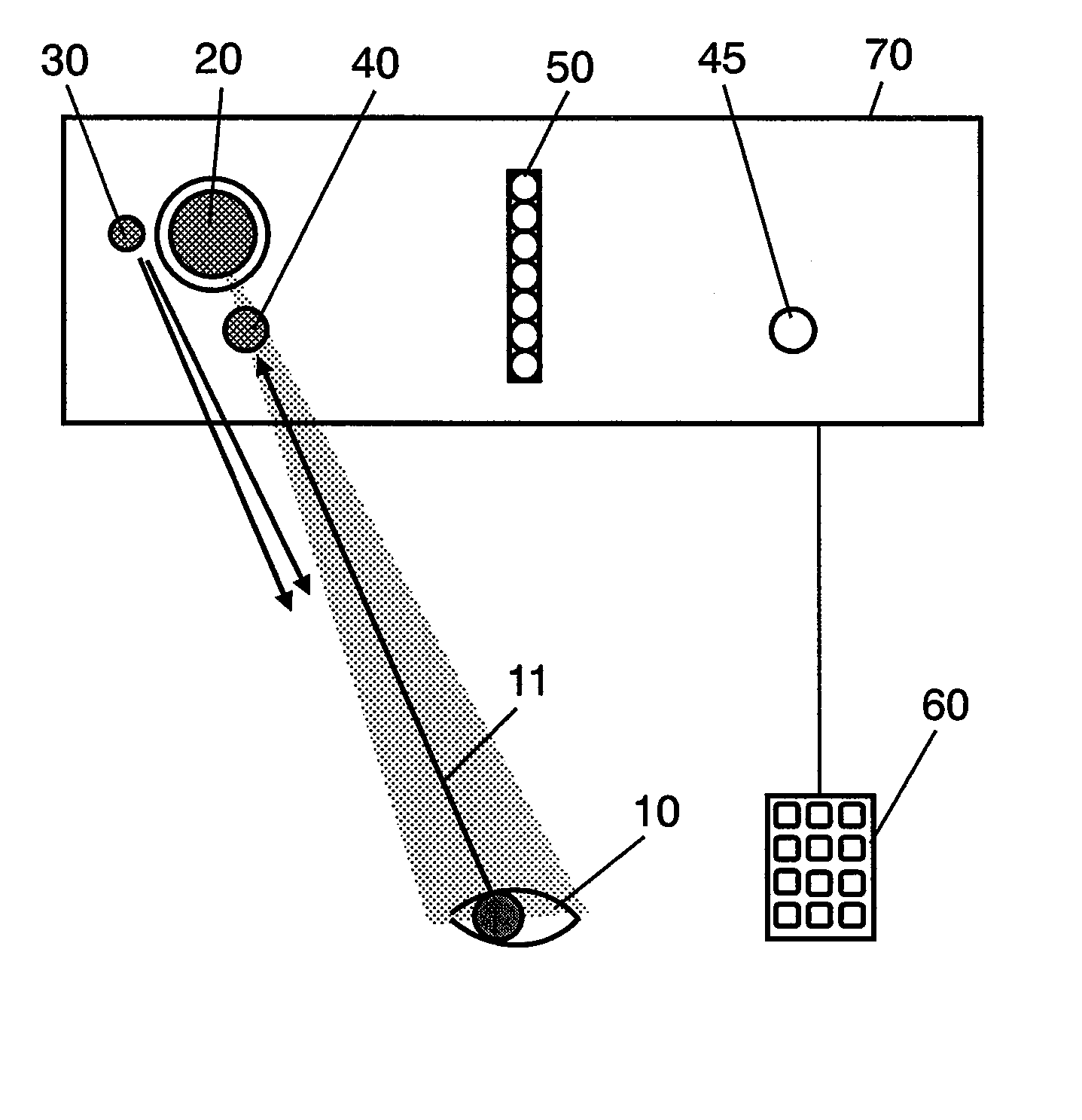
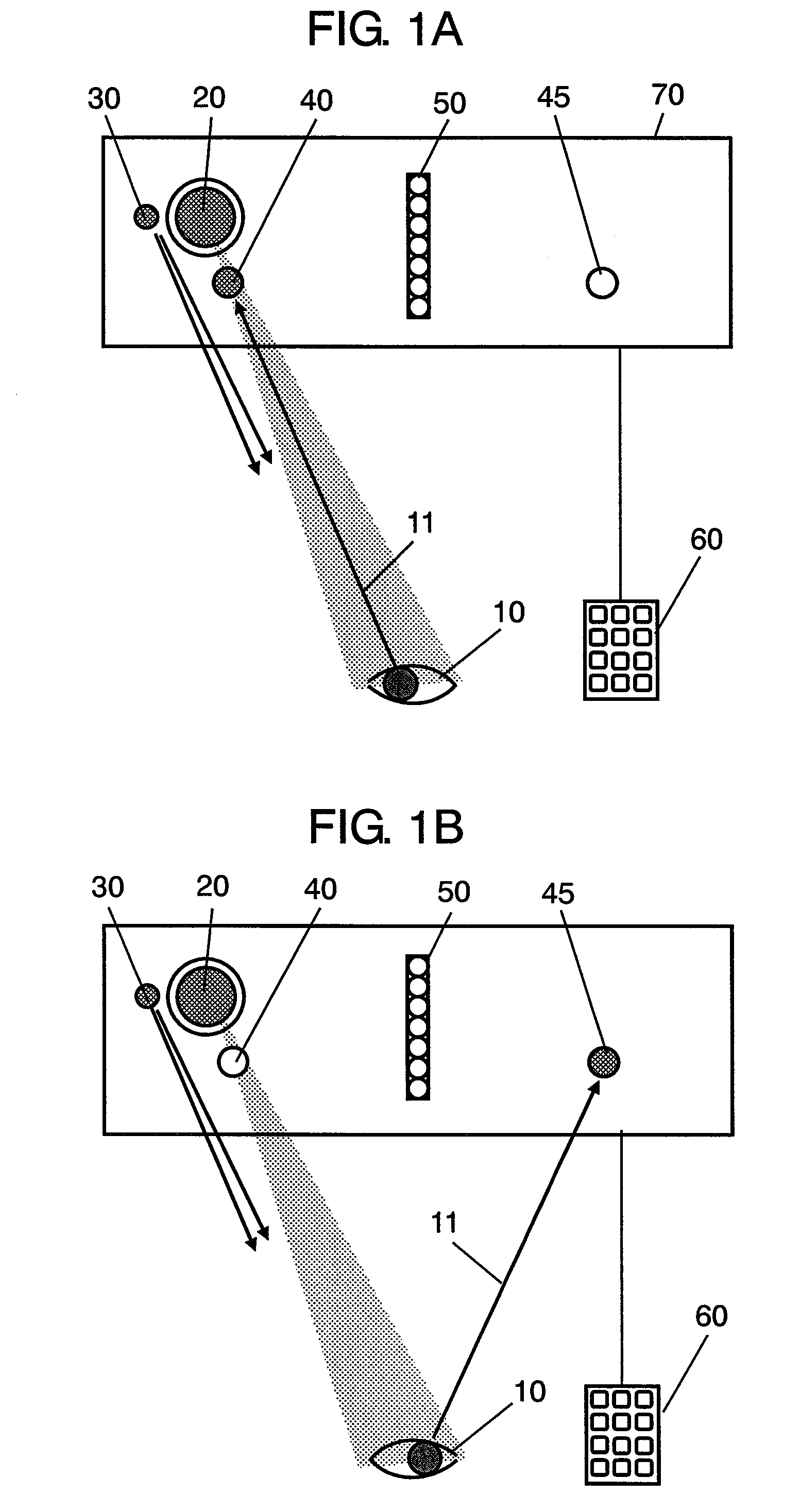
[0038]FIGS. 1A and 1B are schematic diagrams of iris verification devices in accordance with a first exemplary embodiment of the present invention. Camera 20 takes an image of eye 10 of a user. Infrared emitting diode 30 for emitting near-infrared light to illuminate eye 10 is placed near camera 20. Furthermore, first saccade indicator 40 for assisting eye 10 of the user to gaze into camera 20 is placed near camera 20. For example, a visible-light emitting diode for emitting visible light can be used as first saccade indicator 40. Second saccade indicator 45 is placed apart from first saccade indicator 40. In the present embodiment, a distance between eye 10 and camera 20 is set at approximately 35 cm, and an interval between first saccade indicator 40 and second saccade indicator 45 is set at approximately 6.1 cm in such a manner that an angle of saccade becomes approximately 10°.

[0039] Saccade display 50 for indicating a password is placed between first saccade indicator 40 and t...

second exemplary embodiment

[0054]FIGS. 7A and 7B are schematic diagrams of iris verification devices in accordance with the second exemplary embodiment of the present invention. In FIGS. 7A and 7B, the elements similar to those demonstrated in the first embodiment have the same reference marks, and the descriptions thereof are omitted here. The second embodiment differs from the first embodiment in that second camera 25 and infrared emitting diode 35 are placed near second saccade indicator 45.

[0055]FIG. 7A shows a state where sight line 11 of a user is fixed to camera 20 by lighting up first saccade indicator 40, and FIG. 7B shows a state where sight line 11 has moved to second camera 25 by lighting up second saccade indicator 45.

[0056]FIG. 8 is a circuit block diagram of an iris verification device in accordance with the second exemplary embodiment of the present invention. In FIG. 8 also, the elements similar to those demonstrated in the first embodiment have the same reference marks, and the description...


PUM


Abstract

An iris verification device includes: an imaging section for taking an image of an eye of a user; a first saccade indicator for pointing a sight line of the user; a second saccade indicator, which is placed apart from the first saccade indicator, for pointing the sight line of the user; a sight line detecting section for detecting the sight line of the user from the image taken at the imaging section; an iris image sampling section for sampling an iris image from the image taken at the imaging section; a verification section for performing an iris verification act based on the iris image sampled at the iris image sampling section. Variation of the sight line of the user accompanied by the lighting-up of the first saccade indicator or the second saccade indicator is detected as biological reaction by using the sight line detecting section.

Description

TECHNICAL FIELD [0001] The present invention relates to an iris verification device which can prevent an unfair verification act such as impersonation. BACKGROUND ART [0002] In a security system or the like, a method of verification using a pattern of a personal iris is disclosed, for example, in Japanese Translation of PCT Publication H8-504979 or Unexamined Japanese Patent Publication No. 2000-23946. The verification method using an iris has an advantage over a fingerprinting method, because it can be operated in noncontact for the iris and performed by taking an image with a camera from a remote position. Therefore, it is expected to be widespread in the future. [0003] However, an unfair verification act is enabled by copying an iris image of others to a photograph, an artificial eye or the like and using it in iris verification. Accordingly, a method for preventing these unfair verification acts is proposed. As the typical method, for example, a method using biological reaction ...

Claims


Application Information

Patent Timeline
IPC IPC(8): G06K9/00
CPCA61B5/117G06K9/00597G07C9/00158G06K9/00906G07C9/00142G06K9/00604G07C9/33G07C9/37G06V40/19G06V40/18G06V40/45
Inventor TSUKAHARA, SHINICHI
Owner PANASONIC CORP
Why Eureka
Try Eureka