Rotating actuator

a technology of rotating actuators and actuators, applied in the direction of mechanical control devices, gearing, instruments, etc., can solve the problems of high current consumption, inability to enable or disable haptic interfaces, and inability to reverse haptic interfaces, so as to prevent undesired control shaft movements

Inactive Publication Date: 2005-01-18
LEOPOLD KOSTAL GMBH & CO KG
View PDF13 Cites 8 Cited by
  • Summary
  • Abstract
  • Description
  • Claims
  • Application Information

AI Technical Summary

Benefits of technology

Further, this object is achieved according to the present invention by virtue of the fact that, in order to limit the rotation of the control shaft in a direction of rotation, the activated stop device is designed to act on the control shaft in such a way as to prevent the control shaft from executing another rotation in its direction of rotation and to be blocked by the stop device by means of a stop associated with a stop device acting mechanically on the control shaft, and maintain the rotation of the control shaft in a direction of rotation counter to the stop with slip in the stop arrangement. The slip provided by the stop arrangement is dimensioned in such a way that a movement by the control shaft in the direction of rotation counter to the stop can be detected by the angle detection device.
By contrast, such a stop mechanism does not act in the direction of rotation of the control shaft counter to the current direction of rotation, so that the control shaft can be readily actuated in the direction of rotation acting counter to the stop. Therefore, the control shaft is not prevented from moving in a direction of rotation away from the enabled stop mechanism, and its movement can be detected by the angle detection device. Once such a rotation of the control shaft away from the set stop has been detected, the initially activated stop mechanism can be disabled again, so that the control shaft can subsequently be turned in the other, originally limited direction of rotation once again. The two stop mechanisms for limiting the right or left rotation of the control shaft are designed to act mechanically on the control shaft.
As a consequence, the subject matter of this rotating actuator also makes it possible to cancel the stop effect in a direction of rotation just by rotating the rotating actuator away from the stop. Conversely, the stop device blocks the other direction of rotation of the control shaft accordingly.
This rotating actuator also includes an activation device, advantageously electromagnetically actuated, which acts on at least one of the two elements that mechanically interact to generate the haptic interface, i.e., latching cam plate or latching element. Actuating or triggering the activation device makes it possible to enable or disable interaction between the latching cam plate and the one or more latching elements. The activation device can be set up to act on the one or more latching elements, for example, allowing them to engage in the cam plate or lift away from the latching cam plate, depending on the design of the activation device.
Only after the activation device has been triggered is the element carrying the latching cam plate fixed relative to a rotation of the control shaft, so that when the control shaft is subsequently turned, the one or more latching elements are guided by the latching cam plate to generate the desired haptic interface. The advantage to such a configuration is that it prevents undesired control shaft movements caused by a latching element that might not precisely engage in a recess when switching from one haptic interface to another haptic interface. Such haptic interface-induced movements of the control shaft are undesired in some applications.

Problems solved by technology

In these mechanical haptic interface-generating devices, the haptic interface cannot be enabled or disabled and, in particular, the haptic interface also cannot be reversed.
However, the disadvantage to this configuration is that simulating an end stop in this rotating actuator not only results in a high current consumption, but that the counteracting force provided by the electric motor to simulate the end stop can also be surmounted.
Providing the user with an end stop that cannot be so easily surmounted would require that appropriately conceived electrical and electronic components be made available, something which is unfeasible, at least in the automotive industry.
The perceived disadvantage to this stop device that acts mechanically on the control shaft is that a stop can only be established in those positions of the wheel with its pockets relative to the ball in which the ball can engage in a pocket of the wheel.
Therefore, a stop cannot be produced in intermediate positions.

Method used


Image

  • Rotating actuator
  • Rotating actuator
  • Rotating actuator

Examples


Embodiment Construction

)

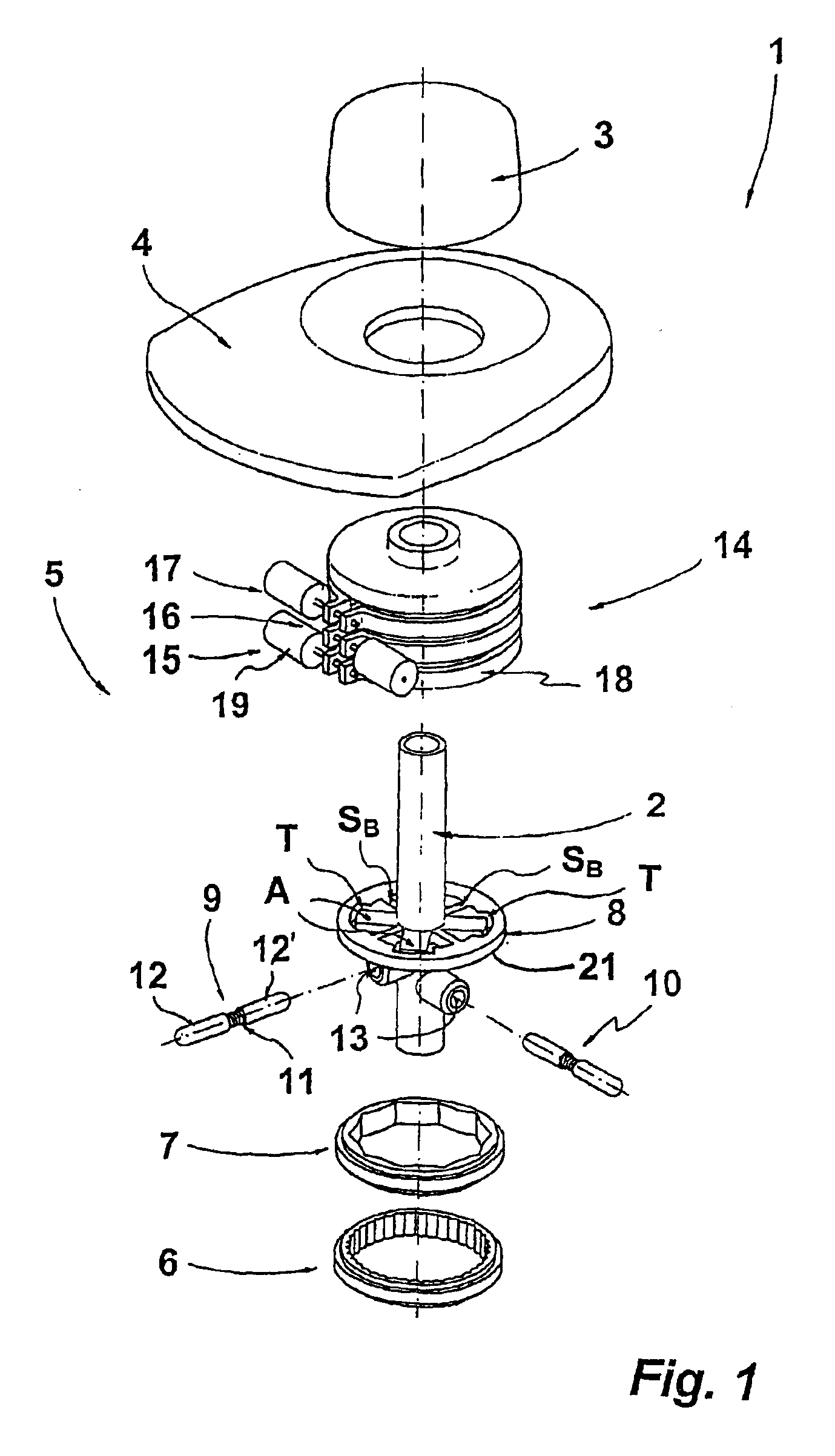
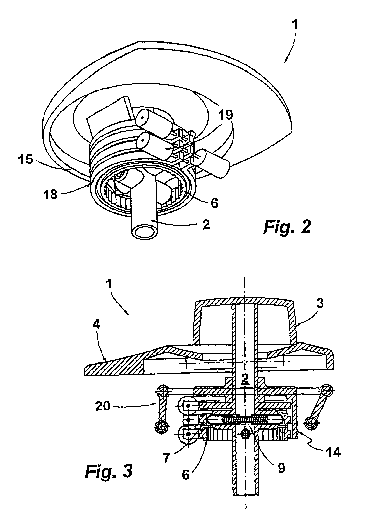
Referring now to FIG. 1, a rotating actuator 1 in accordance with the present invention is shown. Rotating actuator 1 includes a rotatable control shaft 2 at the operator end, of which a turning knob 3 is provided as a handle. Control shaft 2 passes through a mask 4 so that the control shaft segments located below turning knob 3 are covered by the mask.

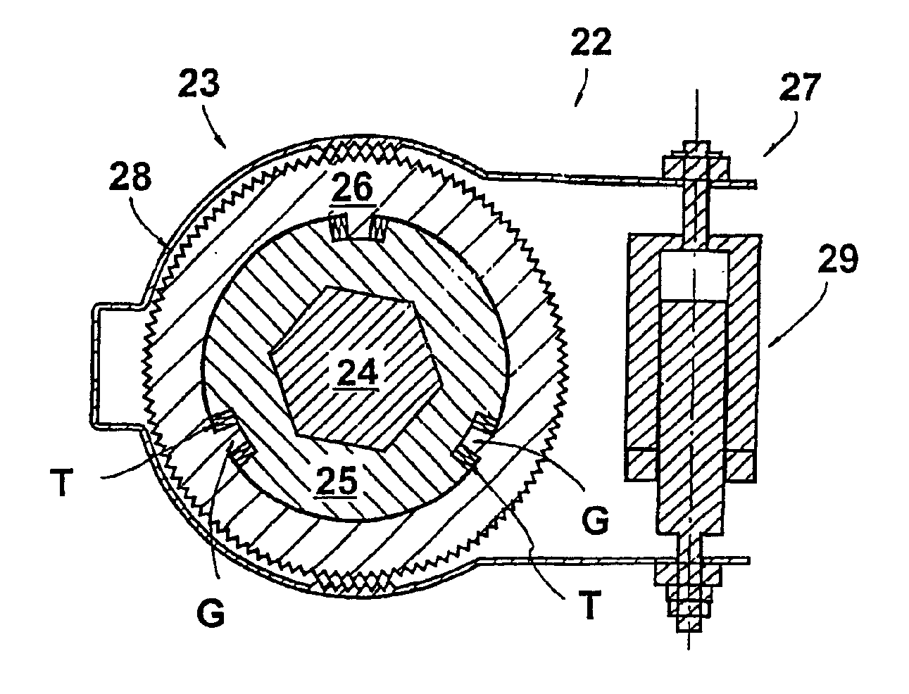
Rotating actuator 1 also includes a haptic perception signal generating device 5 (i.e., haptic interface-generating device). In the embodiment depicted in FIG. 1, haptic interface-generating device 5 includes, for example, two latching cam plate rings 6 and 7, a brake flange 8 connected to control shaft 2, and latching sleeve assemblies 9 and 10. Latching sleeve assemblies 9 and 10 are offset by 90° relative to each other and each include two opposed latching bolts 12 and 12′. Latching bolts 12 and 12′ are placed opposite to each other and are braced against each other by a compression spring 11. Latching bolts 12 and 12′ are each ar...


PUM


Abstract

A rotating actuator includes a shaft (24) and a mechanical stop device (23) for generating a stop to limit the rotation of the shaft in a direction of rotation. The stop device acts upon the shaft to prevent the shaft from rotating further in the direction of rotation by blocking the shaft using a stop device acting mechanically on the shaft while enabling rotation of the shaft in a direction of rotation counter to the stop with slip in a stop arrangement. The slip is configured such that movement of the shaft in the direction of rotation counter to the stop is detectable. The stop device may include two independently triggered, mechanical stop devices. One stop device acts as a stop for limiting the rotation of the shaft to the right, and the other stop device acts as a stop for limiting the rotation of the shaft to the left.

Description

BACKGROUND OF THE INVENTION1. Field of the InventionThe present invention relates to a rotating actuator having a rotatably mounted control shaft and an activatable mechanical stop device for generating a stop to limit the rotation of the control shaft in one or the other direction of rotation, and with an angle detection device for detecting a rotation of the control shaft.2. Background ArtRotating actuators are used, for example, in data input devices, in which the cursor can be controlled in various menu levels by turning the rotating actuator and, if necessary, by pressing or swiveling said rotating actuator. For example, such a rotating actuator can be part of a so-called joystick.One such rotating actuator is known from DE 197 12 049 A1. In this previously known rotating actuator, the gearing of a device for generating a haptic interface is coupled with the control shaft. This device is an electric motor which, when correspondingly actuated, exposes the control shaft to a torq...

Claims


Application Information

Patent Timeline
Patent Type & Authority Patents(United States)
IPC IPC(8): G01D11/00G01D11/16G05G5/00G05G5/06G05G9/047G05G1/08G05G9/00G05G5/03G05G1/00G05G5/28
CPCG01D11/16G05G1/08G05G5/03G05G9/047G05G5/065H01H2003/008G05G2009/04774G05G2009/04781
Inventor OSTER, CHRISTOPH
Owner LEOPOLD KOSTAL GMBH & CO KG
Why Eureka
Try Eureka