Remote control device, electronic device, display device, and game machine control device

a technology of remote control device and display device, which is applied in the field of remote control device, can solve the problems of inconvenient movement of the pointer, poor operation, and inconvenient use of ball pointers, electrostatic pads and joysticks, and achieve the effect of reducing the use of crts

Inactive Publication Date: 2006-06-08
SHARP KK
View PDF5 Cites 8 Cited by
  • Summary
  • Abstract
  • Description
  • Claims
  • Application Information

AI Technical Summary

Benefits of technology

[0006] The present invention has been devised in consideration of these issues, and it is an object thereof to enable movement of a mark on a screen of a display device to be operated smoothly and intuitively.
[0008] With this configuration, when light from a light-emitting element is incident on a light-receiving element constituted by a semiconductor position detection element, the remote control device according to the present invention produces a charge at the position of incidence proportional to the amount of light. This charge is conveyed as a photocurrent to a resistive layer, divided in inverse portion to the distance to output terminals, and taken out as an output electric current. By obtaining the difference or ratio of the electric currents, the light-reception position of light on the light-receiving elements can be detected. Since the light-receiving elements are capable of detecting movement on two axes, namely a horizontal direction and a vertical direction of the light emission point, two-dimensional movement of the light emission point of the light-receiving elements can be detected, and by moving the light emission point, the mark on the screen can be moved by a predetermined amount in a predetermined direction. In this way, by employing semiconductor position detection elements capable of receiving light in two dimensions for the light-receiving elements, a remote control device according to the present invention enables smooth and intuitive operation of a mark on the screen of a display device.
[0016] In the remote control device according to the present invention, it is possible that a light emission intensity of the light-emitting element is adjusted in response to the distance between the light-emitting element and the light-receiving element. Only ordinary dry batteries are incorporated as a power source in the optical operation device provided with the light-emitting element. Ordinarily transmission is carried out with a light emission intensity capable of achieving transmission for the maximum rated distance, and therefore the light emission amount is too strong for the distance at which it is ordinarily used, thus the batteries are used wastefully. By optimizing the electric current that flows to the light-emitting element of the device in response to the distances, the amount of light emitted can be adjusted and battery life can be extended. With this configuration in a remote control device according to the present invention, the distance is detected by the optical operation device, and therefore the amount of light emitted can be regulated based on this information to enable battery life to be extended.
[0017] In the remote control device according to the present invention, it is preferable that a means for enlarging a range of angles of light receivable at the light-receiving element is provided in front of the light-receiving element. With this configuration, movement of the point of emission can be detected using a light-receiving element even when the light has a large angle of incidence, and therefore the range of points of emission in which the light-receiving element can operate becomes wider.
[0019] In an electronic device according to the present invention, output of a light-receiving element may be used to detect ordinary remote controller codes. In this case, it is possible to receive both the mark movement signal and the ordinary remote controller code signals using a single light-receiving element. Furthermore, not only in devices such as digital televisions, set-top boxes, and DVD recorders, but also when operating the pointer on a screen displayed on a liquid crystal projector using a personal computer for example, by arranging the light-receiving device provided with a light-receiving element near to the screen and connecting this to the personal computer, it becomes possible to achieve on-screen operation of the projector from a distant location.
[0020] The present invention may be a game machine control device that uses the present electronic device. In recent years, flat panel televisions using liquid crystal or plasma displays are continuing to become more mainstream than CRTs. In conventional game machine controllers, points of light emission of a scanning line in a CRT are detected for example, and control is carried out based on its position information on the screen. Along with decreased use of CRTs in televisions, it is conceivable that such systems will be unable to be used in future. For this reason, by using a controller of a system of the present invention, it is possible to send controller information to the screen regardless of the presence or absence of scanning lines, and therefore such a controller is suitable as a controller for future game machines.

Problems solved by technology

Although the pointer will move fast if a movement direction button is held down, when the movement distance is large and the button is held down for a long time, the movement of the pointer speeds up acceleratedly such that the location that a user desires to select is passed over and eventually the movement direction buttons must be pushed numerous times again for fine adjustment, and therefore operability is often poor.
Also, ball pointers, electrostatic pads, and joysticks are inconvenient for simple one-handed operation and the movement of the pointer is not intuitive.
It is anticipated that in the near future, channel selection, preprogrammed recording and other such operations will become more complex in devices such as digital televisions, set-top boxes, and DVD recorders due to a greater number and variety of channels, more interactive programs, connection to the Internet, etc.
Also, due to the spread of interactive programs that allow audience participation as well as more comprehensive data telecasts, there is an increasing richness of content in television broadcasting, and accompanying this it is anticipated that on-screen operation of televisions by viewers will be increasingly complicated.
Conventional cross-shaped pointer keys and ball pointing devices are not suited for carrying out such operations.
However, devices provided with these PSDs have also failed to solve these problems in terms of enabling smooth and intuitive two-dimensional movement of a pointer.

Method used


Image

  • Remote control device, electronic device, display device, and game machine control device
  • Remote control device, electronic device, display device, and game machine control device
  • Remote control device, electronic device, display device, and game machine control device

Examples


Embodiment Construction

[0033] Hereinafter, embodiments of the present invention will be described with reference to the accompanying drawings.

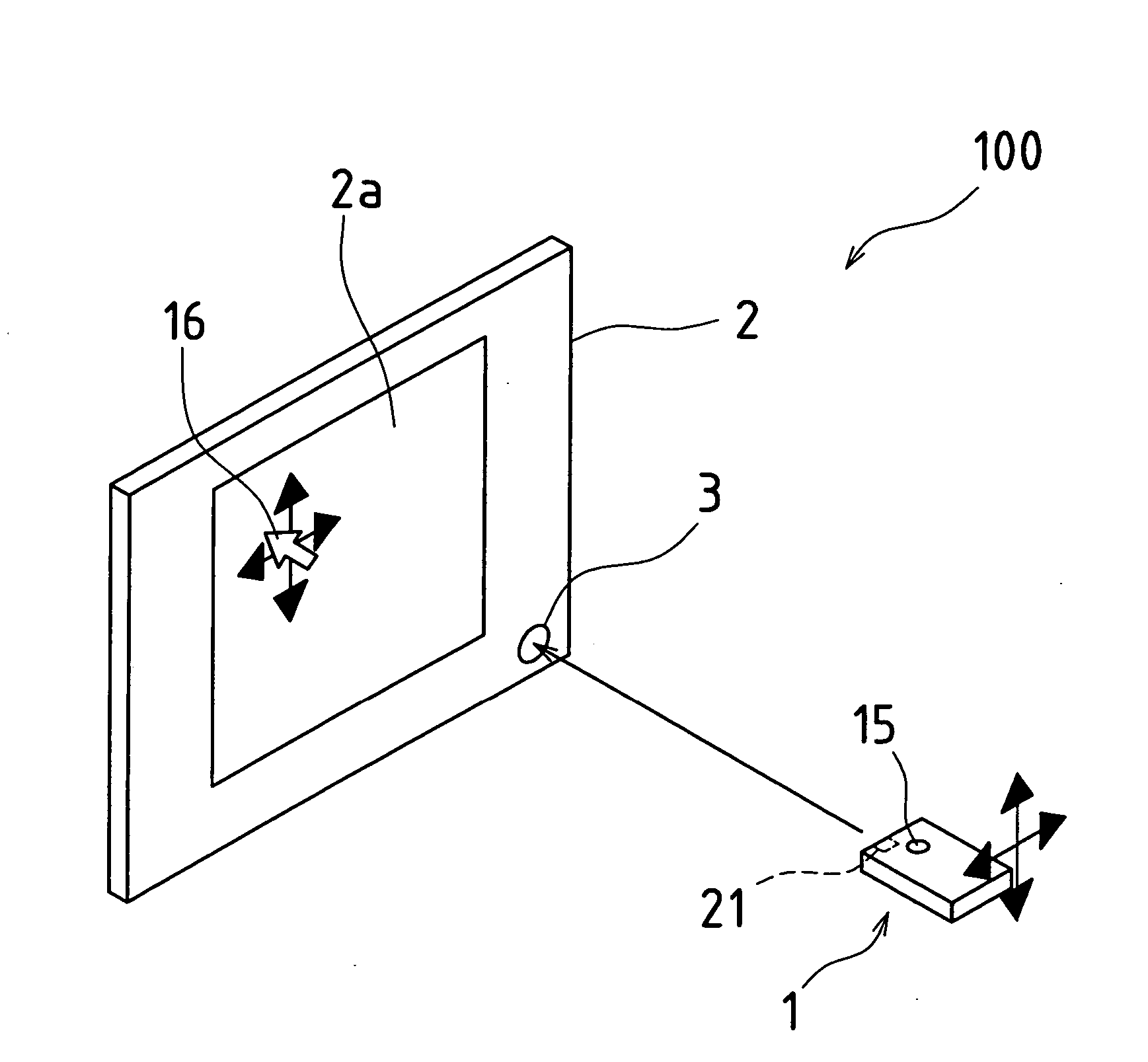
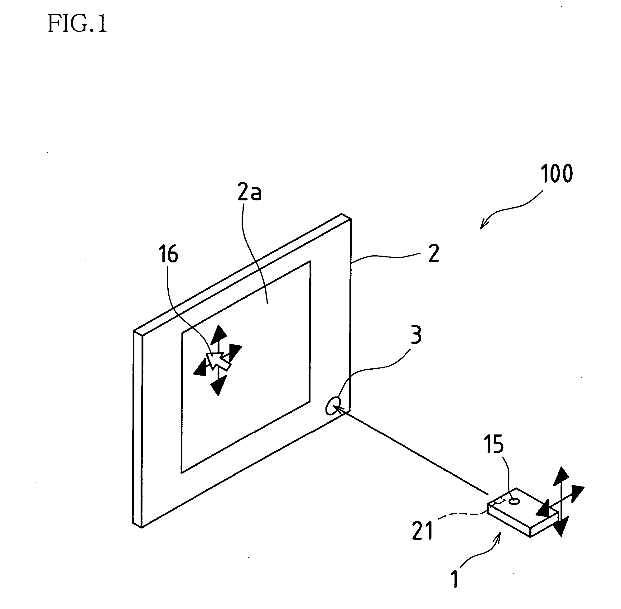
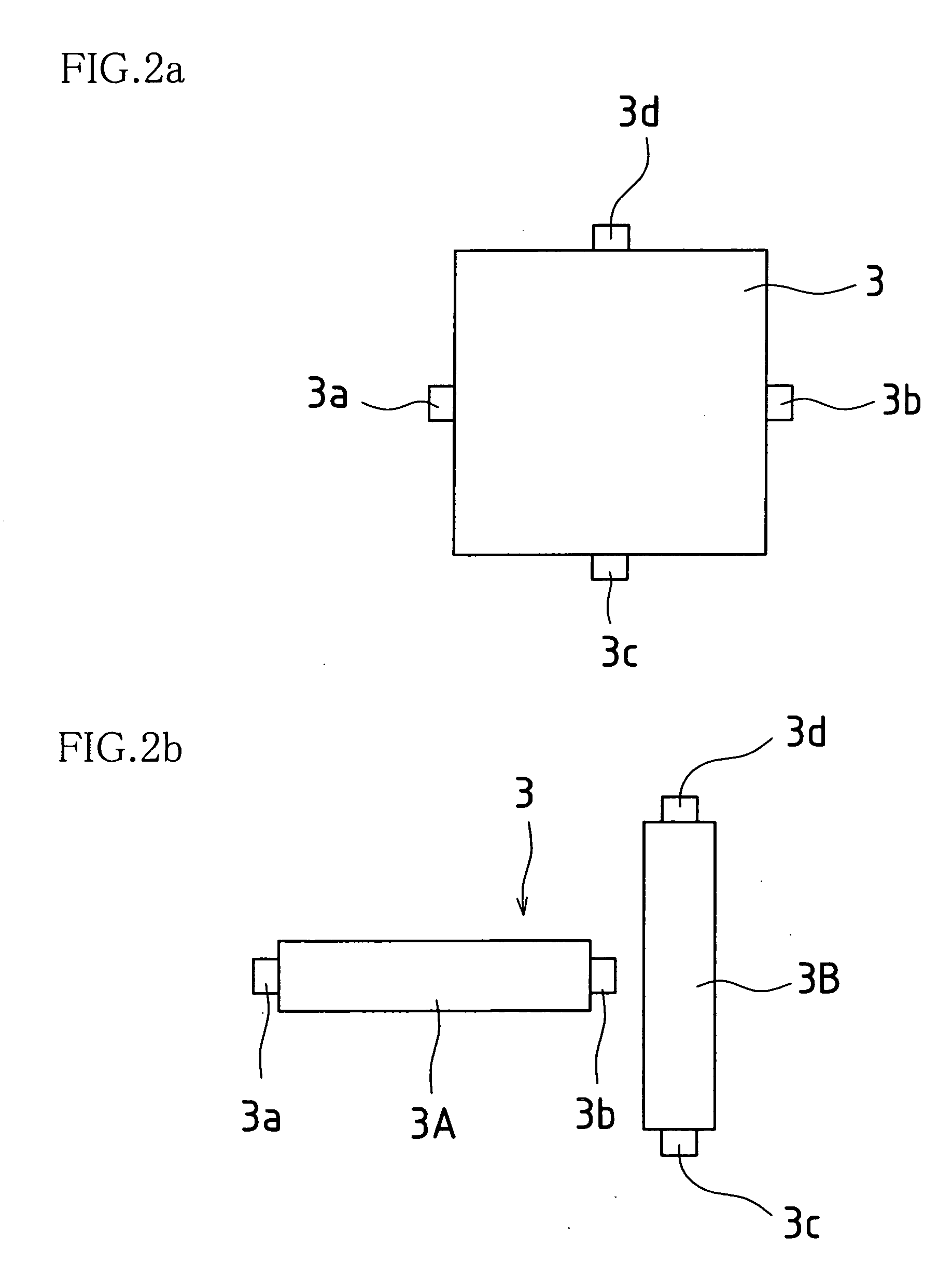
[0034]FIG. 1 is a perspective view showing an outline of a remote control device according to an embodiment of the present invention. FIG. 2 is a front view showing an arrangement of light-receiving elements. FIG. 3 is a block diagram of a light-receiving device side. FIG. 4 is a cross-sectional view showing a PSD detection principle.

[0035] The remote control device 100 shown in FIG. 1 is provided with a pointing device 1 as an optical operation device provided with a light-emitting element 21 that emits infrared light for example, a display device 2 having a screen 2a, and a PSD 3 as a light-receiving element arranged at the display device 2.

[0036] As shown in FIG. 4, the PSD 3 is a component in which a P layer is formed at a surface of a flat plate of silicon, with an N layer at a back face, and an I layer in between. When a spot of light L is incident, an elec...


PUM


Abstract

A remote control device provided with a means for receiving light from a light-emitting element 21 at a light-receiving element 3 and detecting from a signal thereof a movement amount of a mark 16 on a screen 2a of a display device 2 so as to cause movement of the mark such as a pointer on the screen of the display device in response to a movement amount of a light emission point H of the light-emitting element, wherein the light-receiving element is provided with a semiconductor position detection element, and moreover, is configured to be capable of detecting movement of the light emission point in a horizontal direction and a vertical direction, and causes the mark on the screen of the display device to move due to the signal from the light-receiving element.

Description

BACKGROUND OF THE INVENTION [0001] This application claims priority under 35 U.S.C. § 119(a) on Patent Application No. 2004-346759 filed in Japan on Nov. 30, 2004, the entire contents of which are hereby incorporated by reference. [0002] The present invention relates to a remote control device that enables a user to speedily and intuitively move a mark on a screen of a display device in a distant position using a free movement in space, and particularly relates to remote control devices, electronic devices, display devices, and game machine control devices that simplify operation on a screen that is displayed on a television or other type of display. [0003] Conventionally, cross-shaped pointer keys or ball pointing devices that have been added to remote controllers are available as devices that operate a pointer as a mark on a screen of a display device in a distant position. Furthermore, coordinate input devices equipped with electrostatic pads or a joystick are also generally avai...

Claims


Application Information

Patent Timeline
Patent Type & Authority Applications(United States)
IPC IPC(8): G06M7/00G06F3/033G06F3/0346H04N5/00H04Q9/00
CPCA63F13/06G06F3/0304G06F3/0346H04N21/42222H04N5/4403H04N2005/4428H04N2005/4432G06F3/038A63F13/213H04N21/42204H04N21/42206
Inventor HISAKAWA, KOHJIYOSHIFUSA, KOHJIMATSUMURA, KAZUHIKOKASHIDA, HAJIMEAOKI, FUMIHIKO
Owner SHARP KK
Why Eureka
Try Eureka