Working machine

a technology of working machine and working frame, which is applied in the direction of snow cleaning, electric propulsion mounting, transportation and packaging, etc., can solve the problems of troublesome control of working machine b>200/b>, waste of energy, and often fluctuating load size, so as to improve operability of working machine and reduce idle state , the effect of simple control of working machin

Inactive Publication Date: 2006-09-05
HONDA MOTOR CO LTD
View PDF10 Cites 12 Cited by
  • Summary
  • Abstract
  • Description
  • Claims
  • Application Information

AI Technical Summary

Benefits of technology

[0016]The upper limit value of the correction coefficient is determined at the timing at which the working part is turned on with the work on / off switch. Because of this, the correction coefficient in the low idle state is originally high. Even if the engine speed falls somewhat in correspondence with the size of the load, the correction coefficient is kept at a high value. Consequently, even if work is started in the low idle state, the speed of the electric motor is to some extent maintained. Therefore, the shift from the low idle state to an optimal working state can be made rapidly, and the operability of the working machine improves.
[0017]Furthermore, the frequency with which it is necessary to adjust the throttle aperture when the load fluctuates can be made low, and controlling the working machine becomes simple. Also, it is not necessary to set the throttle angle constantly high in order to reduce the trouble of throttle control, and fuel consumption can be reduced.
[0018]The operator can suitably determine (1) the setting of the throttle aperture and (2) the timing at which the working part was turned on with the work on / off switch. By this means, the speed of the engine as of when the working part is turned on with the work on / off switch (the reference speed) can be set freely, and it is possible to run the working machine in a more optimal state.
[0019]Preferably, the control part of this invention is provided in advance with a plurality of correction coefficient maps having different correction coefficient characteristics, and when determining the correction coefficient selects one map from among the plurality of correction coefficient maps in correspondence with the speed of the engine as of when the working part was turned on. In this case, the speed of the electric motor can be controlled more finely and optimally.

Problems solved by technology

However, during snow-removal work, the size of the load often fluctuates.
When it is necessary to adjust the throttle aperture like this every time the load fluctuates, controlling the working machine 200 is troublesome.
On the other hand, if the throttle aperture is constantly set high to reduce the trouble of control, energy is wasted and this is therefore undesirable.

Method used


Image

  • Working machine
  • Working machine
  • Working machine

Examples


Embodiment Construction

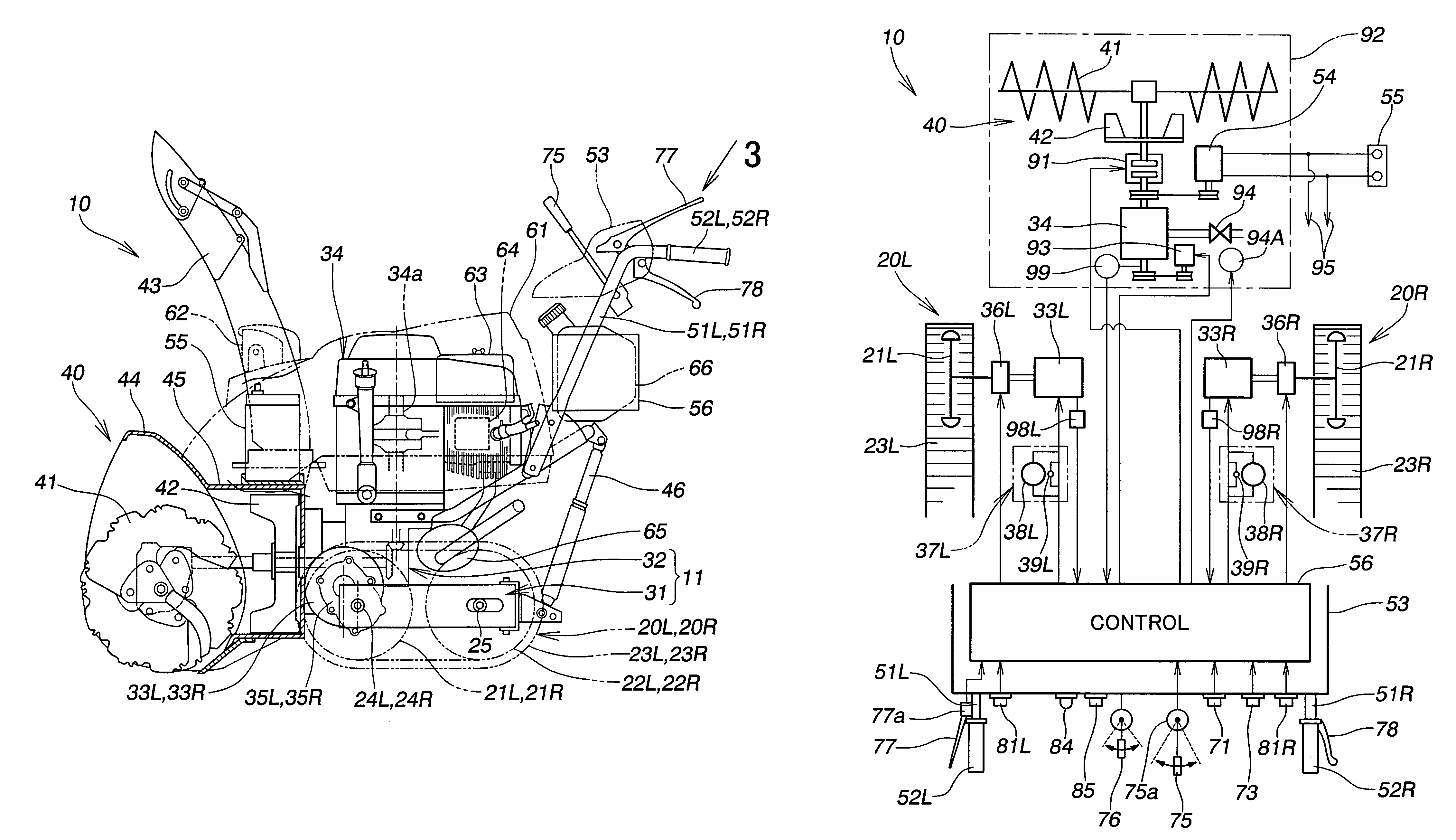
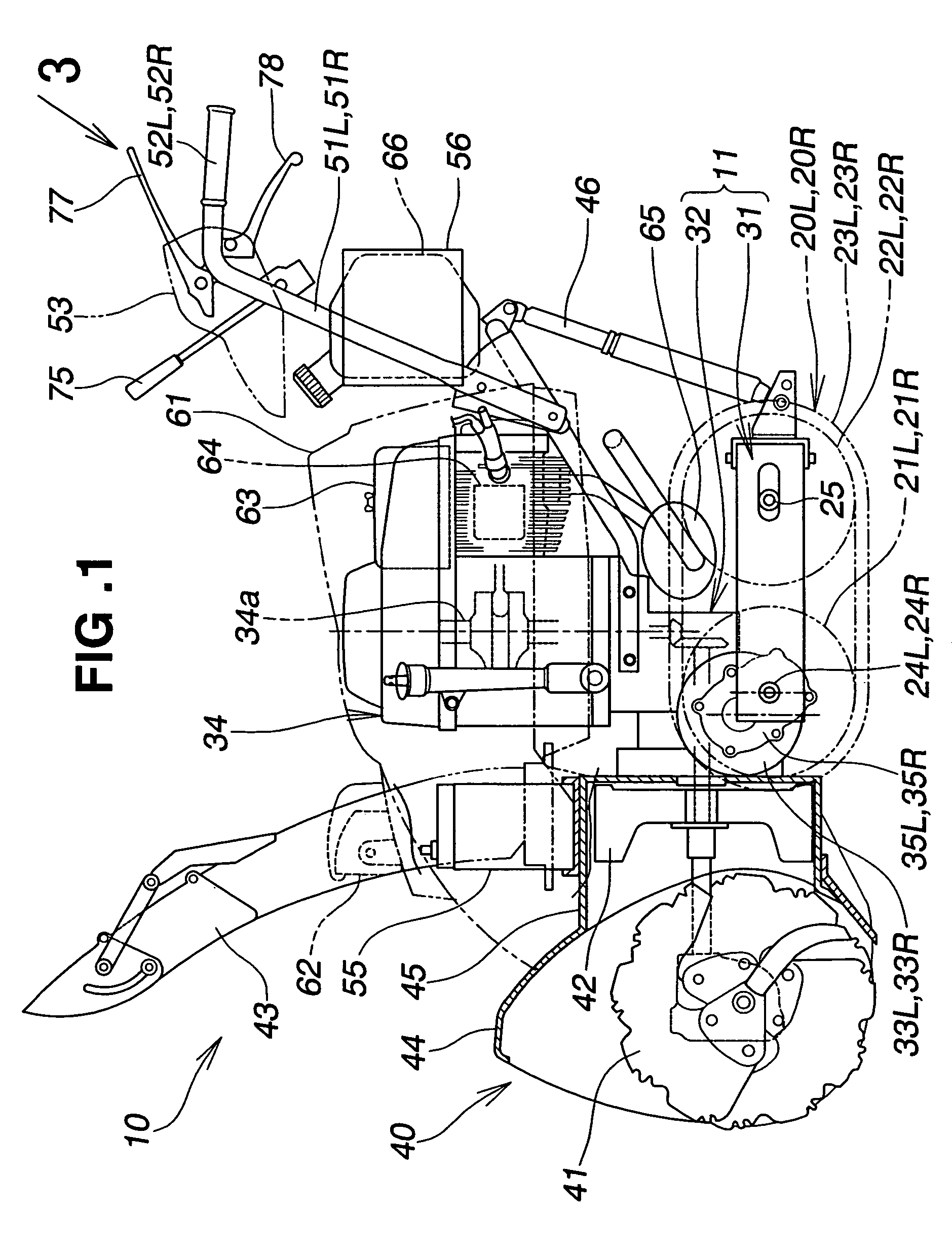
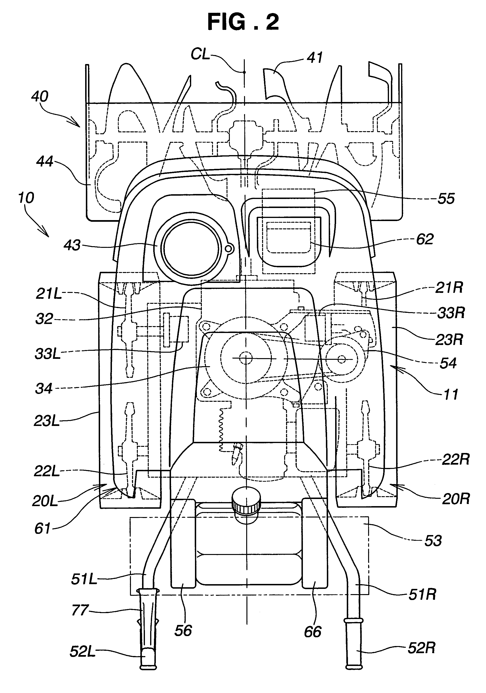
[0034]A preferred embodiment of a working machine will now be described, and as a suitable embodiment of a working machine the example of a snow-remover will be used, as shown in the drawings.

[0035]As shown in FIG. 1 and FIG. 2, a snow-remover 10, which is a working machine, includes a machine body 11 made up of a transport frame 31 and a transmission case 32.

[0036]The transport frame 31 has left and right transporting parts 20L, 20R. The transmission case 32 is attached to the transport frame 31 in such a way that it can swing up and down. Left and right electric motors 33L, 33R are mounted on left and right side parts of the transmission case 32. An engine (internal combustion engine) 34 is mounted on an upper part of the transmission case 32. A snow-removal working part 40 is mounted on the front of the transmission case 32. Left and right operating handles 51L, 51R extend upward and rearward from the top of the transmission case 32. A control panel 53 is provided between the lef...


PUM


Abstract

A working machine has a machine body, an engine mounted on the machine body, an electric motor mounted on the machine body, a working part driven by the engine during a working state of the working part for performing a working operation, and a transporting part driven by the electric motor for transporting the working machine during the working operation. A control part controls rotation of the electric motor by setting a speed of the engine as a reference speed at a time at which the working state of the working part is initiated, determining a correction coefficient corresponding to a present speed of the engine from a correction characteristic having a correction coefficient corresponding to the reference speed of the engine, determining an acceleration of the transporting part in accordance with an actual travel speed of the transporting part, obtaining a corrected acceleration by multiplying the acceleration determined by the second determining means by the correction coefficient determined by the first determining means, and accelerating the speed of the electric motor in accordance with the obtained corrected acceleration.

Description

FIELD OF THE INVENTION[0001]The present invention relates generally to a working machines and, more specifically, to a working machine such as a snow remover having a working apparatus, a transporting apparatus, an engine as the drive source for the working apparatus, and an electric motor as the drive source for the transporting apparatus.BACKGROUND OF THE INVENTION[0002]Common working machines having both a working part and a transporting part driven by an engine appear for example in JP-A-1-163304 and JP-UM-A-3-32617.[0003]However, there are working machines in which the drive sources of the working part and the transporting part are separate. For example working machines having a working part driven by an engine and a transporting part driven by an electric motor appear in JP-B-53-5210 and JP-A-2001-271317. If the working part is drive-controlled with an electric motor like this, there is the advantage that the working machine can be made more maneuverable.[0004]As an example of...

Claims


Application Information

Patent Timeline
Patent Type & Authority Patents(United States)
IPC IPC(8): E01H5/09B60K1/02B62D51/04B62D55/06E01H5/04
CPCB60K1/02E01H5/04B62D55/06B62D51/04
Inventor WAKITANI, TSUTOMUSHIMIZU, NORIKAZUKAWAKAMI, TOSHIAKI
Owner HONDA MOTOR CO LTD
Why Eureka
Try Eureka