AI technical title is built by Patsnap AI team. It summarizes the technical point description of the patent document.
a specimen and instrument technology, applied in the direction of instruments, mechanical measuring arrangements, mechanical roughness/irregularity measurements, etc., can solve the problem of limited repeatability of x-y repositioning of stylus profilometers, limited lateral positioning resolution of conventional stylus profilometers, and lack of repeatable nanometer or sub-nanometer x-y positioning capability
Inactive Publication Date: 2006-09-05
KLA CORP
View PDF60 Cites 31 Cited by
Summary
Abstract
Description
Claims
Application Information
AI Technical Summary
This helps you quickly interpret patents by identifying the three key elements:
Problems solved by technology
Method used
Benefits of technology
Problems solved by technology
The large size of the X-Y stage in the stylus profilometer limits the lateral positioning resolution of the conventional stylus profilometer.
Thus the repeatability of X-Y repositioning of stylus profilometers is limited to about 1 micrometer; such device lacks the capability for repeatable nanometer or sub-nanometer X-Y positioning capability.
If the CMP processing is not functioning properly, it may cause a recess in the tungsten plug or via hole and, therefore, affect the size and depth of the tungsten plugs and via holes.
This may lead to a variation of capacitance and electrical resistance across the surface of the semiconductor wafer which adversely affect the operation of electronic circuits fabricated on the wafer.
The problem becomes particularly accute in vary large scale integration circuits where the size of transistors and other electronic devices have been continually reduced.
While profilometers are able to provide a measure of the surface topography of the wafer, conventional profilometers lack the resolution to discover the shape and depth of the tungsten plugs or via holes, for example.
Conventional profilometers lack the position / positioning capability to allow precise alignment of submicron features with the scan.
Hence, if profilometers are used for monitoring the CMP process, even though the global planarization of the sample and the relative height of points that are spaced apart on the wafer can be monitored, a precise local morphology of the surface cannot be measured.
While scanning probe microscopes (SPMs) do have the precision positioning capability to allow precise alignment of submicron features with the scan path, SPM devices do not have a precise long range and repeatable motion, so that it is difficult to use SPM devices to find out the relative locations of two points that are spaced far apart on the wafer surface or the height relationship between two tungsten plugs or via holes that are spaced apart on the wafer.
Even if a number of local images acquired by the SPM are stitched together, the global topography of the surface is lost, and height differences between points that are spaced that are spaced apart by distances beyond the range of SPM devices cannot be precisely measured.
Moreover, data correlation between a number of local images of the SPM is cumbersome, time consuming and requires significant duplication of resources.
Method used
Image
Click on the blue label to locate the original text in one second.
Reading with bidirectional positioning of images and text.
Examples
Embodiment Construction
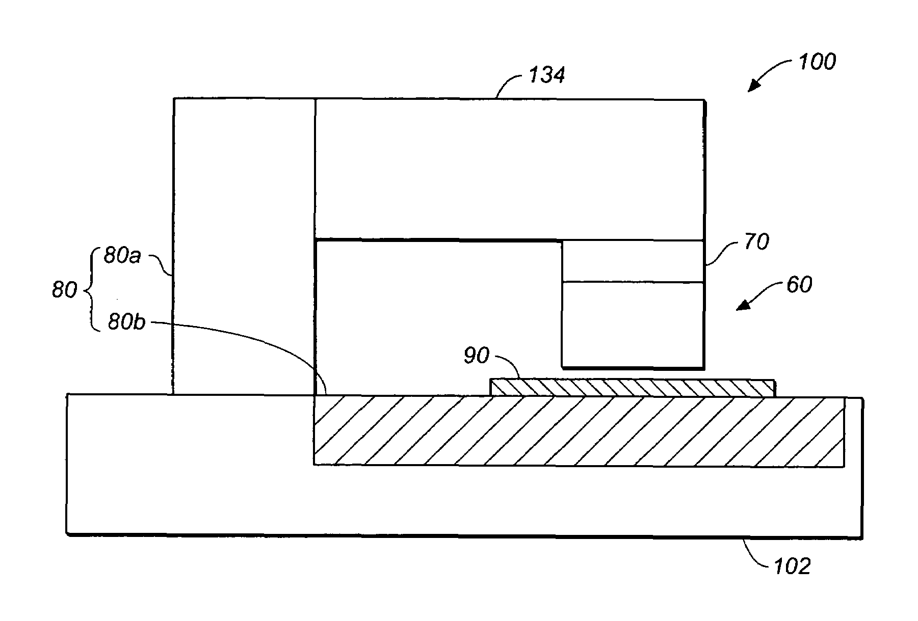
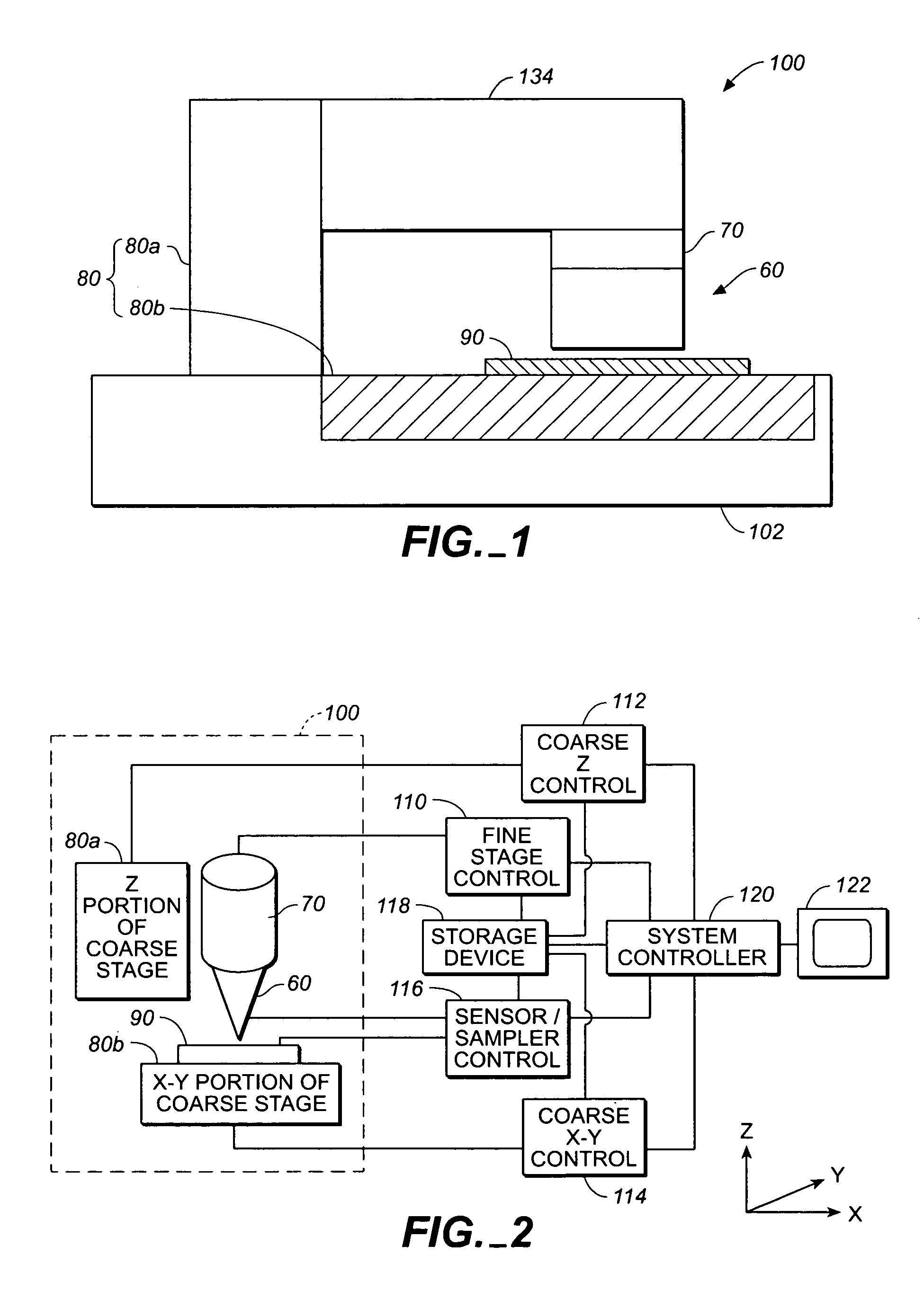
[0062]FIG. 1 is a schematic view of a dual stage scanning instrument 100 to illustrate the preferred embodiment of the invention. Since the sensor assembly 60 may be much lighter than the sample or specimen 90, it may be desirable to support the sensor by means of the fine stage 70 and use the XY portion 80b of the coarse stage 80 to support the specimen or sample. The fine stage is in turn connected to and supported by the Z portion 80a of the coarse stage. Thus as shown in FIG. 1, the scanning instrument 100 includes a sensor assembly 60 connected to and supported by a fine stage 70 which in turn is connected to and supported by the Z portion 80a of the coarse stage 80. A sample 90 is supported by the XY portion 80b of the coarse stage 80. The Z portion 80a and X-Y portion 80b of coarse stage 80 are connected to and supported by base 102 as shown in FIG. 1.
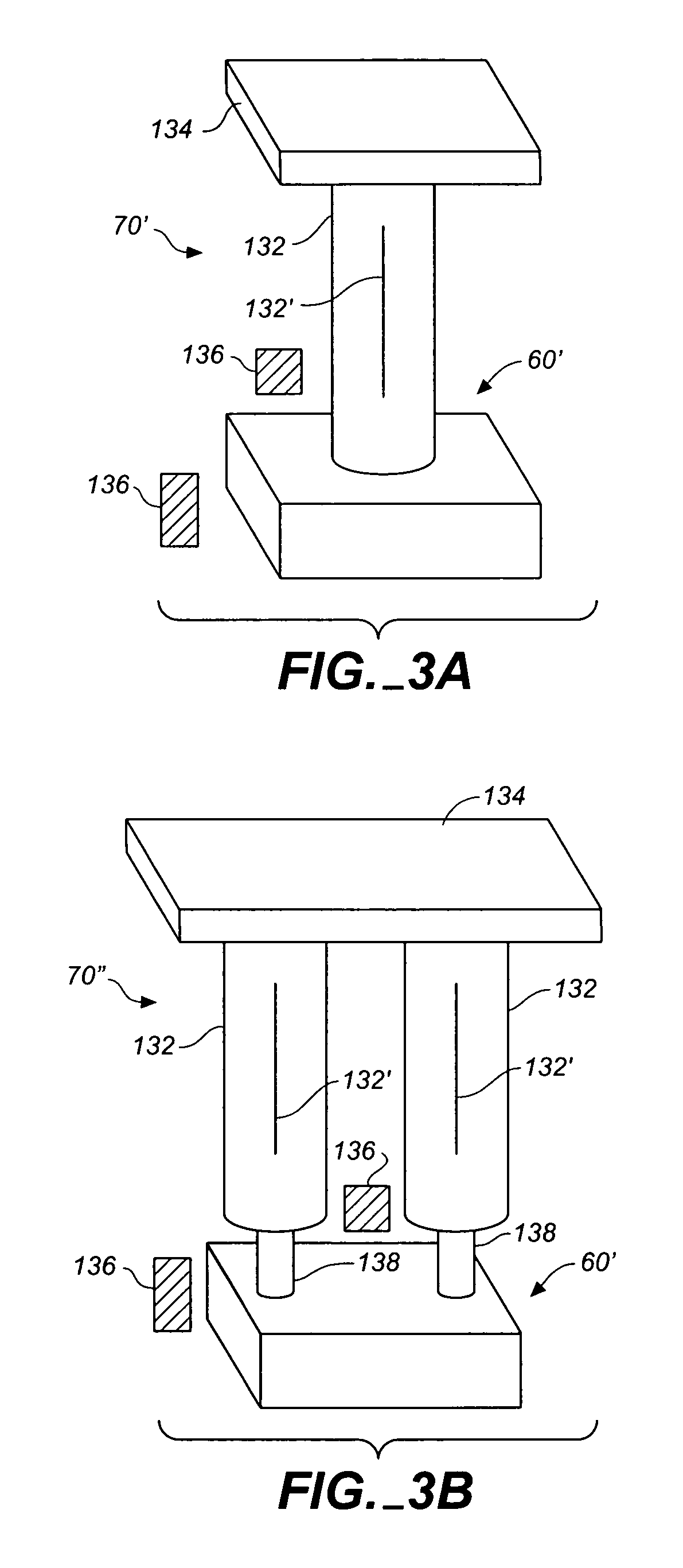
[0063]Fine stage 70 preferably has a lateral resolution of about 1 to 50 Angstroms (0.1 to 5 nanometers), although a lateral r...
PUM
Property
Measurement
Unit
radius
aaaaa
aaaaa
radius
aaaaa
aaaaa
length
aaaaa
aaaaa
Abstract
A dual stage scanning instrument includes a sensor for sensing a parameter of a sample and coarse and fine stages for causing relative motion between the sensor and the sample. The coarse stage has a resolution of about 1 micrometer and the fine stage has a resolution of 1 nanometer or better. The sensor is used to sense the parameter when both stages cause relative motion between the sensor assembly and the sample. The sensor may be used to sense height variations of the sample surface as well as thermal variations, electrostatic, magnetic, light reflectivity or light transmission parameters at the same time when height variation is sensed. By performing along scan at a coarser resolution and short scans a high resolution using the same probe tip or two probe tips at fixed relative positions, data obtained from the long and short scans can be correlated accurately.
Description
CROSS-REFERENCE TO RELATED APPLICATIONS[0001]This application is a divisional of U.S. patent application Ser. No. 10 / 133,510, filed Apr. 25, 2002, now abandoned which is a divisional of U.S. patent application Ser. No. 09 / 900,806, filed Jul. 6, 2001, now abandoned which is a continuation of U.S. patent application Ser. No. 09 / 199,634, filed Nov. 25, 1998, now U.S. Pat. No. 6,267,005, which is a continuation of U.S. patent application Ser. No. 08 / 730,641, filed Oct. 11, 1996, now U.S. Pat. No. 5,948,972, which is a continuation-in-part of U.S. patent application Ser. No. 08 / 598,848, filed Feb. 9, 1996, now abandoned, which is a continuation-in-part of U.S. patent application Ser. No. 09 / 362,818, filed Dec. 22, 1994, now U.S. Pat. No. 5,705,741. This application is also related to U.S. patent application Ser. No. 08 / 728,480, filed Oct. 11, 1996, now U.S. Pat. No. 5,866,806, referred to hereinafter as the “companion application.”BACKGROUND OF THE INVENTION[0002]This invention relates i...
Claims
Application Information
Patent Timeline
Application Date:The date an application was filed.
Publication Date:The date a patent or application was officially published.
First Publication Date:The earliest publication date of a patent with the same application number.
Issue Date:Publication date of the patent grant document.
PCT Entry Date:The Entry date of PCT National Phase.
Estimated Expiry Date:The statutory expiry date of a patent right according to the Patent Law, and it is the longest term of protection that the patent right can achieve without the termination of the patent right due to other reasons(Term extension factor has been taken into account ).
Invalid Date:Actual expiry date is based on effective date or publication date of legal transaction data of invalid patent.

