Self-adjusting pliers

a self-adjusting, plier technology, applied in the field of pliers, can solve the problems of small jaw movement relative to each other in the end, affecting the quality of pliers,

Inactive Publication Date: 2006-09-05
I D L TECH TOOLS
View PDF40 Cites 9 Cited by
  • Summary
  • Abstract
  • Description
  • Claims
  • Application Information

AI Technical Summary

Benefits of technology

[0013]In one form, the pliers includes a releasable overcenter lock for the jaws. In this version, there is a downwardly extending lobe on the control arm. A release arm is pivotably connected to the lower arm and has a release pad disposed to contact the lobe of the control arm when the release arm is pivoted. In operation, the control arm moves to an overcenter position when the clamping force is fully applied. This overcenter position may be released to unlock the jaws from the workpiece either by pulling the handles apart, or by manually pivoting the release arm. The overcenter locking is readily released by pulling the upper arm and the lower arm apart when the clamping force is small, but is more conveniently released by operating the release arm when the clamping force is large.
[0017]In operation, with the jaws separated and not contacting the workpiece, the jaw arm, the lower arm, the control arm, and the engagement mechanism initially rotate relative to the upper arm as an interconnected unit about the main pivot. An anti-squat mechanism aids in maintaining the fixed geometrical relationship of these elements during the initial rotation. A main spring reacts between this interconnected unit and the upper arm, and specifically between the jaw arm and the upper arm. The main spring weakly biases the interconnected unit away from the upper arm to initially keep the jaws separated. The hand force applied by the user through the upper arm and the lower arm overcomes this biasing to move the jaws toward contact with the workpiece. When the jaws contact the workpiece, the shifter begins to rotate to apply the hand force of the user to the workpiece as the clamping force. As the contact pressure increases further, the force multiplication effect comes into play to produce a clamping force that is greater than the user would otherwise produce. The workpiece is thereby clamped between the jaws with a maximum clamping force that is controllable through the force adjuster. Release of the hand force by the user reverses the process. If the pliers is the locking embodiment or the switchable embodiment operated in the locking mode, the lock automatically engages to hold the workpiece securely even though the user relaxes the force applied through the upper arm and the lower arm. The locking may be unlocked by operating the release arm.

Problems solved by technology

Commercial versions of this pliers are useful, but have significant drawbacks.
Perhaps the most significant problem with the pliers made according to the '598 patent is that the jaws move slightly relative to each other in an end-to-end manner as they are clamped down onto a workpiece.
The surfaces of soft workpieces such as brass or copper may be marred as a result.
Another problem with the pliers of the '598 patent is that they do not lock to the workpiece, an important convenience in some uses of pliers.
Conventional overcenter locking pliers provide adjustability in the size of the workpiece that may be gripped through a screw adjustment to the pivoting position of the control arm, but this adjustability is not automatic in the sense of the pliers of the '598 patent.
This pliers can be inconvenient to use for some sizes of workpieces, suffers from some of the problems of the pliers of the '598 patent, does not achieve a large gripping force, and may unexpectedly unlock when large objects are being gripped.

Method used


Image

  • Self-adjusting pliers
  • Self-adjusting pliers
  • Self-adjusting pliers

Examples


Embodiment Construction

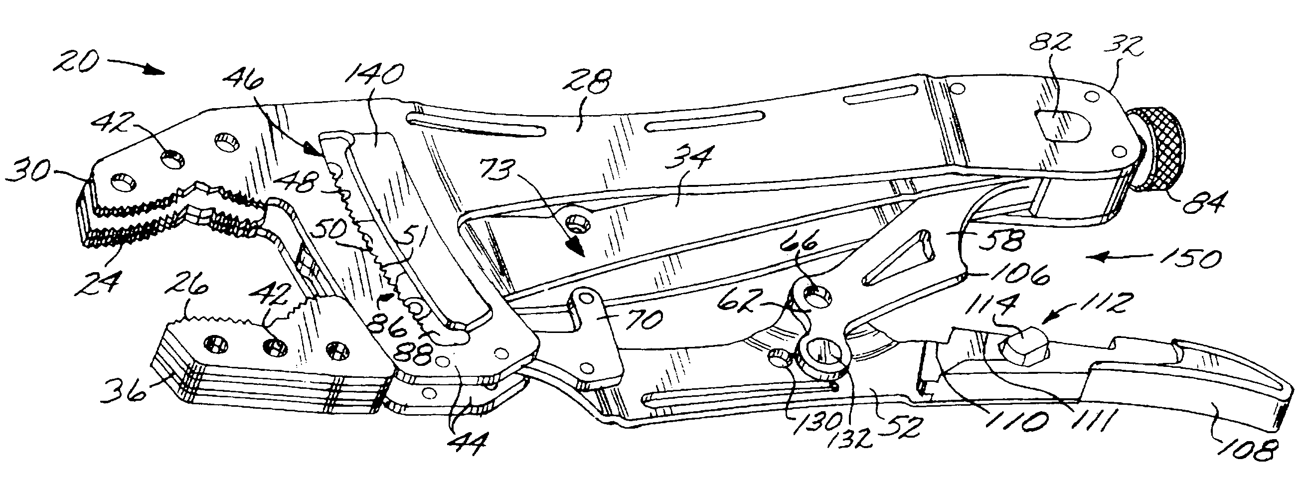
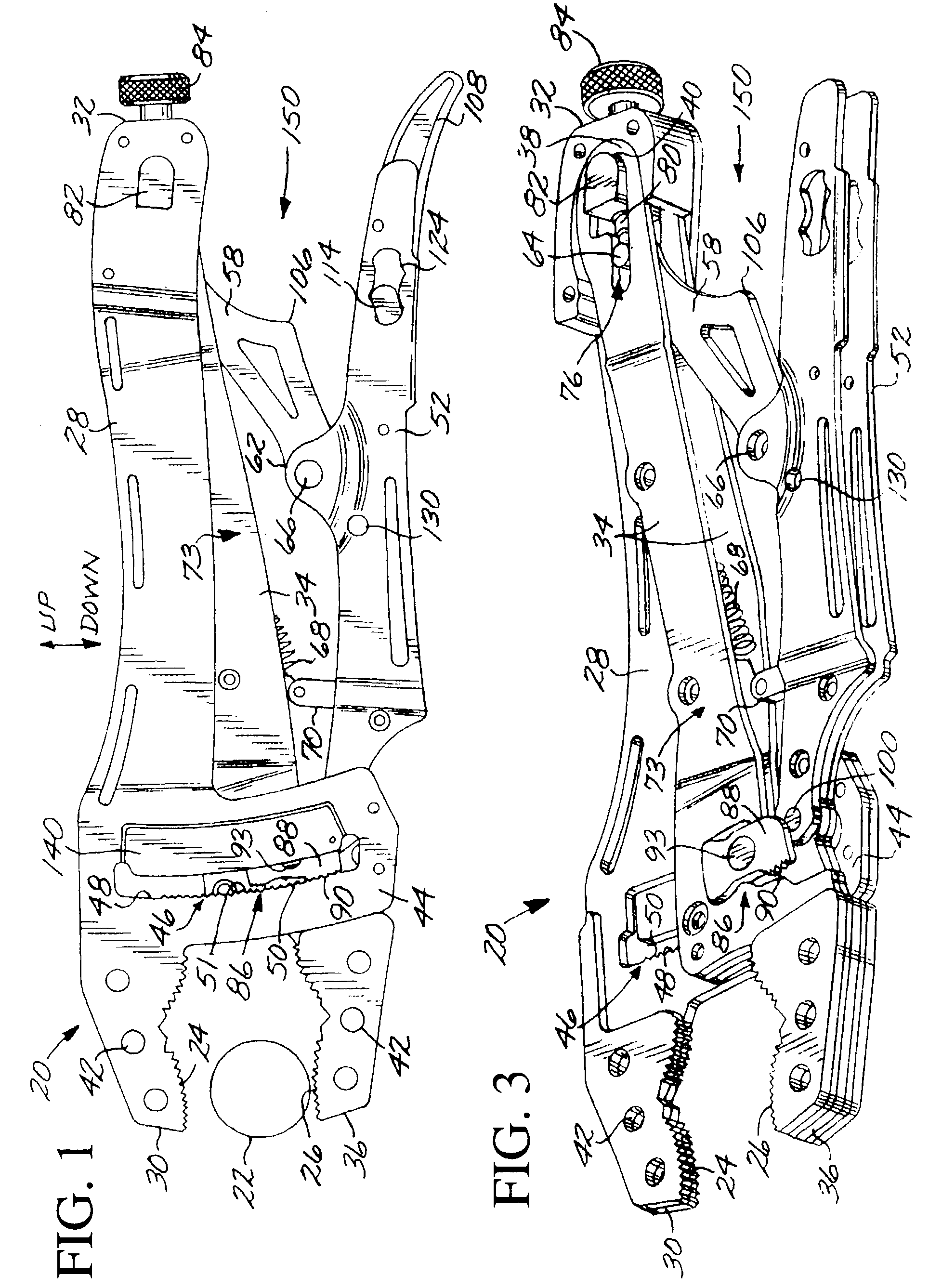
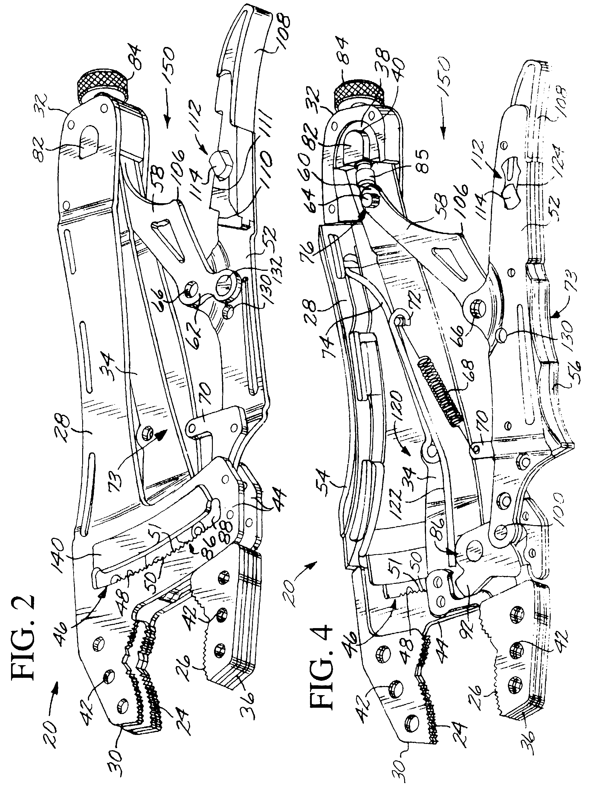
[0025]FIGS. 1–6 illustrate a self-adjusting pliers 20 according to the invention. FIG. 1 is an elevational view, and FIGS. 2–4 show the same pliers 20 with portions of the structure progressively removed to illustrate the internal structure and mechanics. FIGS. 5–6 are details. “Up” and “down” reference directions are indicated on several of the figures and apply to all of the embodiments. In the figures, rivets that are present to hold the structure together are not shown because their heads tend to obscure the views of the relevant structure. The appropriate rivet holes are visible.

[0026]As illustrated in FIG. 1, the self-adjusting pliers 20 is a hand tool that is operable to grasp a workpiece 22 between an upper jaw 24 and a lower jaw 26. An upper arm 28 has a first end 30 and a second end 32. The upper jaw 24 is at the first end 30 of the upper arm 28, and is integral with the remainder of the upper arm 28 in the depicted embodiment.

[0027]As best seen in FIG. 3, a jaw arm 34 has...


PUM


Abstract

A self-adjusting pliers is operable to grasp a workpiece between an upper jaw and a lower jaw. The pliers includes an upper arm having a first end and a second end, with the upper jaw at the first end. A jaw arm has a first end and a second end. The second end of the jaw arm is pivotably connected to the upper arm at a main pivot adjacent to the second end of the upper arm, so that the first end of the jaw arm is movable in a circular arc relative to the main pivot. The lower jaw is at the first end of the jaw arm in movable facing relation to the upper jaw so that the workpiece may be grasped between the upper jaw and the lower jaw. An engagement mechanism releasably engages the jaw arm to the upper arm at an engagement position responsive to a movement of the jaw arm relative to the upper arm and responsive to a size of the workpiece grasped between the upper jaw and the lower jaw, to thereby prevent rotation of the jaw arm relative to the upper arm.

Description

CROSS-REFERENCE TO RELATED APPLICATIONS[0001]This application is a continuation of application Ser. No. 09 / 942,095, filed Aug 28, 2001, now U.S. Pat. No. 6,748,829, for which priority is claimed and whose disclosure is incorporated by reference; which is a continuation of application Ser. No. 09 / 594,191, filed Jun. 14, 2000, now U.S. Pat. No. 6,279,431, for which priority is claimed and whose disclosure is incorporated by reference; which in turn is a continuation-in part of application Ser. No. 09 / 334,055, filed Jun. 15, 1999, now U.S. Pat. No. 6,212,978, for which priority is claimed and whose disclosure is incorporated by reference. This application also claims the benefit of U.S. Provisional Application No. 60 / 390,007, filed Jun. 18, 2002, whose disclosure is incorporated herein by reference.FIELD OF THE INVENTION[0002]This invention relates to pliers, and, more particularly, to a self-adjusting pliers that grips workpieces of various sizes without manual adjustment.BACKGROUND O...

Claims


Application Information

Patent Timeline
Patent Type & Authority Patents(United States)
IPC IPC(8): B25B7/04B25B7/10B25B7/12
CPCB25B7/123B25B7/10
Inventor SEBER, BRETT P.CARMICHAEL, ERIC B.
Owner I D L TECH TOOLS
Why Eureka
Try Eureka