Pivotal connection of a table leg to a frame

a technology of pivoting connection and table leg, which is applied in the field of pivoting connection of the table leg to the frame, to achieve the effect of reducing the cost of the table, facilitating the assembly of the table, and quick and easy assembly

Inactive Publication Date: 2006-09-05
LIFETIME PRODUCTS
View PDF41 Cites 55 Cited by
  • Summary
  • Abstract
  • Description
  • Claims
  • Application Information

AI Technical Summary

Benefits of technology

[0034]A further aspect is the table can be constructed without requiring the use of mechanical fasteners or tools. As discussed above, the frame, legs and retaining members can be secured to the table top without requiring the use of mechanical fasteners. In addition, the legs can be connected to the frame and the support braces without the use of mechanical fasteners. Thus, the table can be assembled without using mechanical fasteners such as screws, bolts, and rivets. Advantageously, this may decrease the cost of the table because fewer components are required to assemble the table. In addition, the table can be more quickly and easily assembled because it does not require the use tools to attach the various components. This may also allow the consumer or purchaser to more easily assemble the table.
[0035]Another aspect is the table top may include a downwardly extending lip and the inner surface of the lip may include a number of serrations, notches, ribs, and / or struts that are sized and configured to increase the strength, rigidity and / or flexibility of the lip. Advantageously, the uneven inner surfaces of the lip may increase the strength, rigidity and / or flexibility of the table top. In addition, the corners of the table top may also include one or more serrations, notches, ribs, and / or struts that are sized and configured to increase the strength, rigidity and / or flexibility of the corners.
[0036]A still further aspect of the table is the table top may be constructed from two or more pieces. The two or more pieces are preferably pivotally connected to allow the table top to fold into a compact position. For example, the table top may be constructed from a first piece and a second piece with one or more interlocking portions and one or more overlapping portions. These interlocking and / or overlapping portions allow the two pieces of the table top to be securely interconnected to form a rigid table top. Significantly, the table top constructed from two or more pieces may allow the table to be more easily transported and / or stored because, for example, it may be folded in half.

Problems solved by technology

In addition, because the interior portion of the table top is generally hollow, that creates a lightweight table top.

Method used


Image

  • Pivotal connection of a table leg to a frame
  • Pivotal connection of a table leg to a frame
  • Pivotal connection of a table leg to a frame

Examples


Embodiment Construction

[0063]The present invention is generally directed towards a table with a frame that can be connected to the table top without using mechanical fasteners. The principles of the present invention, however, are not limited to tables with frames that can be connected to table tops without using mechanical fasteners. It will be understood that, in light of the present disclosure, the table disclosed herein can be successfully used in connection with other types of furniture and structures.

[0064]Additionally, to assist in the description of the table, words such as top, bottom, front, rear, right and left are used to describe the accompanying figures. It will be appreciated, however, that the table can be located in a variety of desired positions—including various angles, sideways and even upside down. A detailed description of the table now follows.

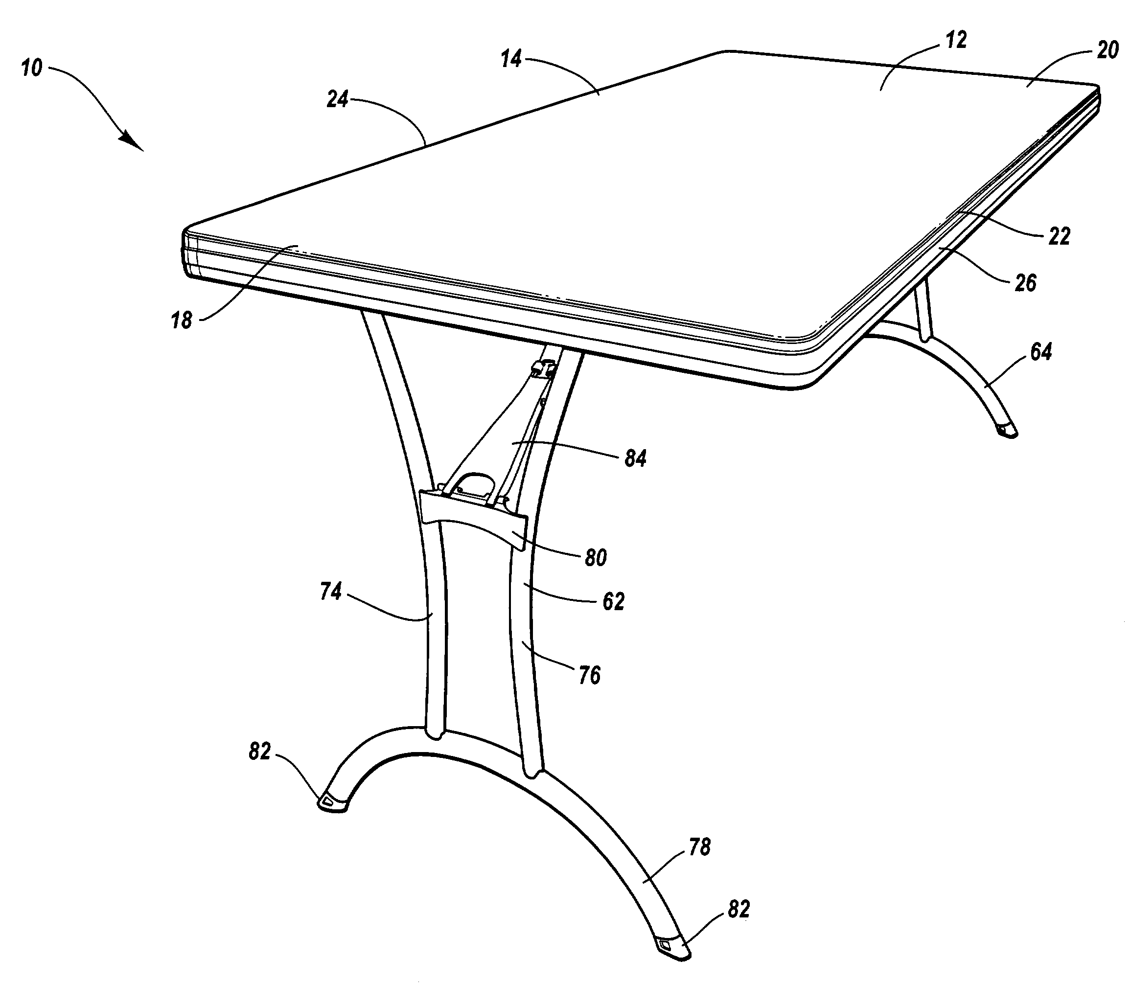
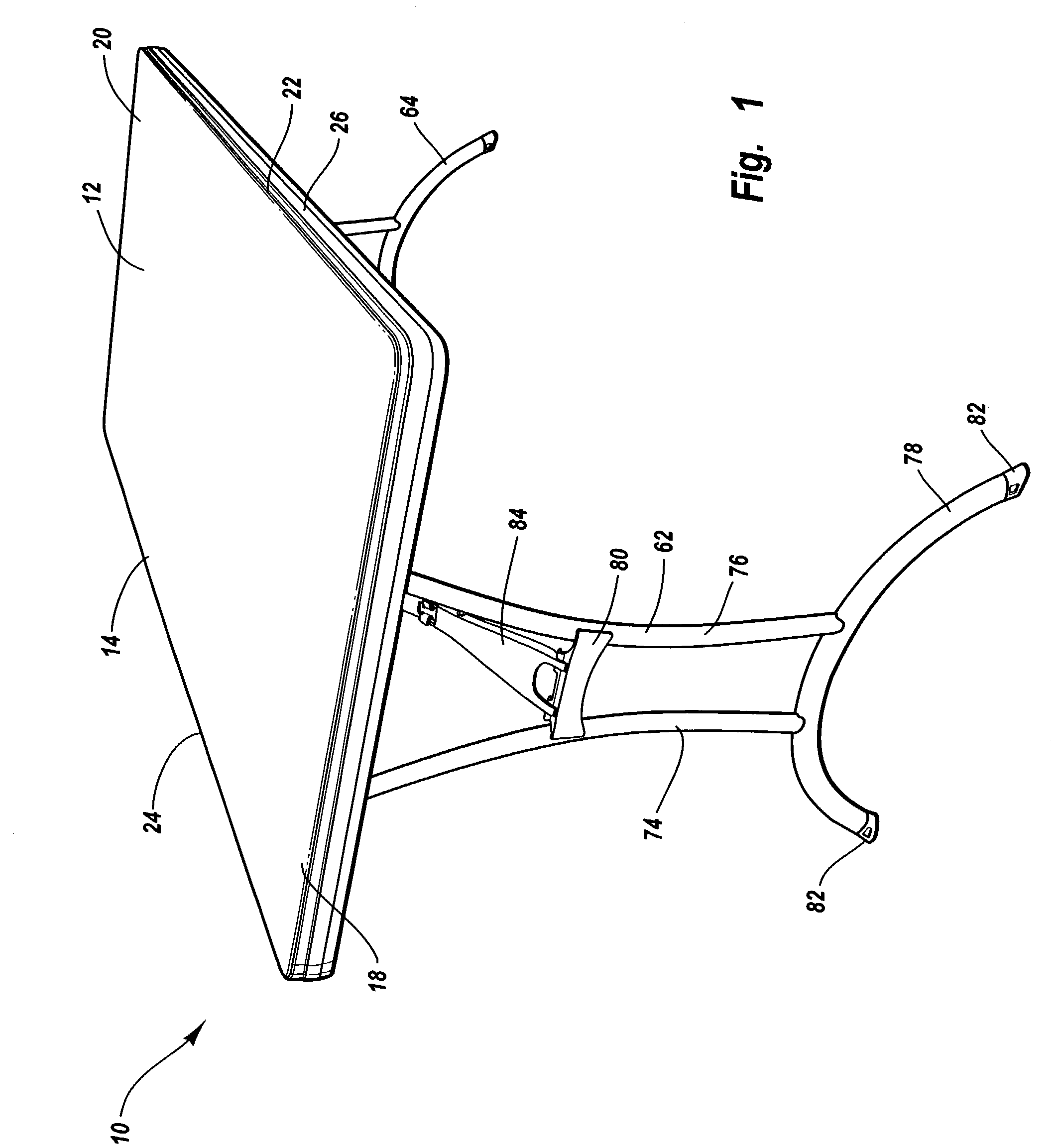
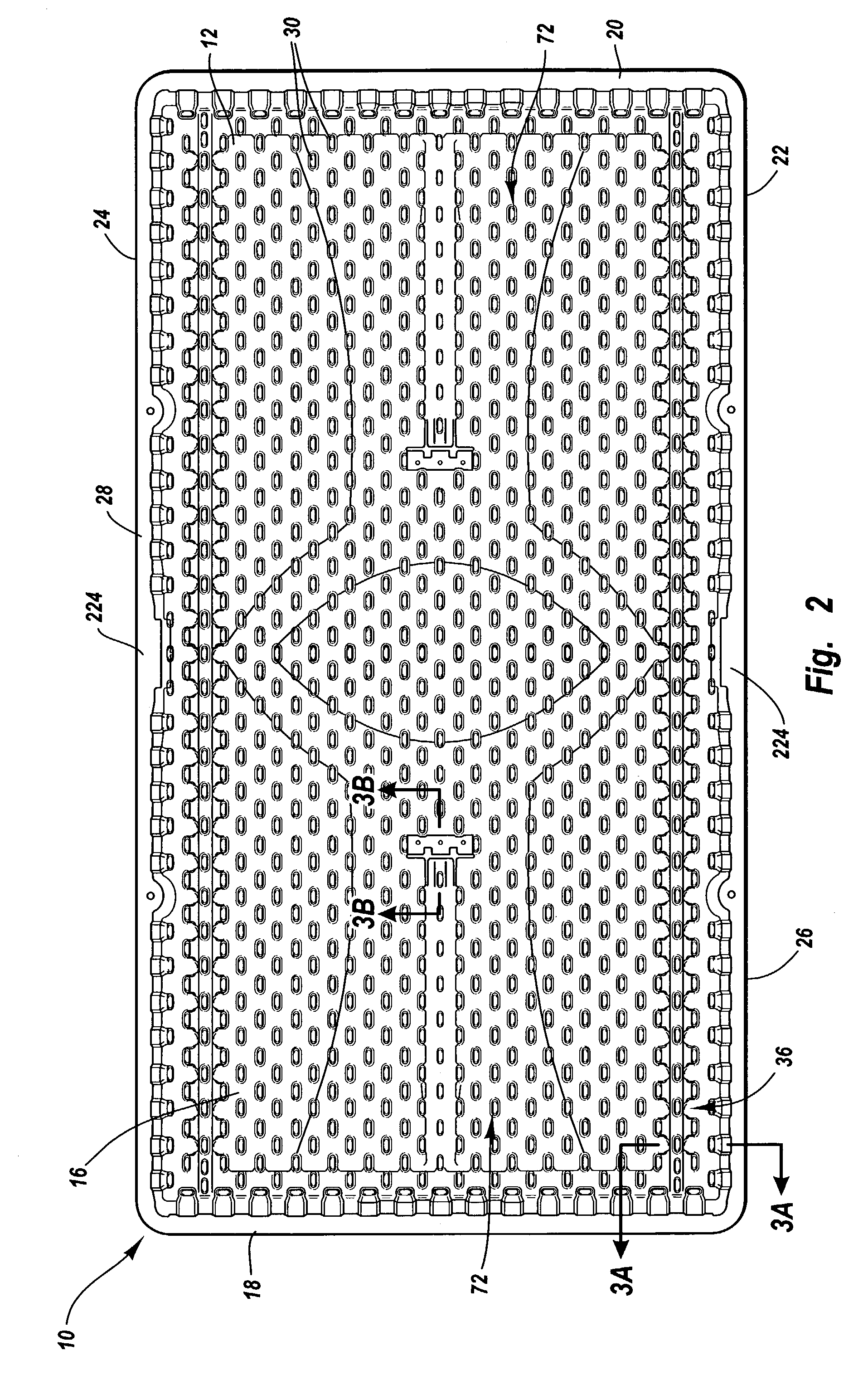
[0065]As shown in FIGS. 1 and 2, the table 10 includes a table top 12 with an upper surface 14, a lower surface 16, a first end 18, a second ...


PUM

PropertyMeasurementUnit
widthaaaaaaaaaa
lengthaaaaaaaaaa
widthaaaaaaaaaa

Abstract

A table includes a table top, a frame, and a pair of non-circular openings are formed in the frame. The table also includes a leg that is movable between an extended position and a collapsed position relative to the table top. A connecting rod connects the leg to the pair of openings in the frame and the connecting rod preferably has a non-circular cross-sectional configuration. The connecting rod and the openings in the frame are sized and configured to loosely attach the leg to the table when the leg is in the collapsed position. The connecting rod and the openings, however, are sized and configured to securely attach the leg to the table when the leg is in the extended position.

Description

CROSS-REFERENCE TO RELATED APPLICATIONS[0001]The present application claims priority to and the benefit of U.S. Provisional Patent Application Ser. No. 60 / 371,486, entitled UTILITY TABLE WITH BLOW-MOLDED TABLE TOP, which was filed on Apr. 9, 2002, and is hereby incorporated by reference in its entirety.BACKGROUND OF THE INVENTION[0002]1. Field of the Invention[0003]The present invention is generally related to tables and, in particular, to tables with blow-molded plastic table tops.[0004]2. Description of Related Art[0005]Many different types of tables are well known and used for a variety of different purposes. For example, conventional tables may include legs that are pivotally attached to the table top and the legs may be movable between a use position in which the legs extend outwardly from the table top and a storage position in which the legs are folded against the table top. Large, portable tables with folding legs are often referred to as “banquet tables” and these tables ar...

Claims


Application Information

Patent Timeline
Patent Type & Authority Patents(United States)
IPC IPC(8): A47B3/00A47B3/087A47B13/00A47B13/02A47B13/08A63B63/08B29C49/00F16B12/24
CPCA47B3/087A47B3/0912A47B13/003A47B13/021A47B13/08F16B12/24A63B63/083B29C49/0031B29K2995/0077B29K2995/0082B29K2995/0089B29L2031/448
Inventor STRONG, L. CURTIS
Owner LIFETIME PRODUCTS
Why Eureka
Try Eureka