

Control valve
a control valve and valve body technology, applied in the direction of valve details, multiple-way valves, mechanical equipment, etc., can solve the problems of inability to direct control the volume flow or the pressure in the working connection, the use of such a directional valve is greatly restricted, and the solution is therefore not particularly advantageous, etc., to achieve cost-effective manufacture, simple structure, and dynamic behavior
- Summary
- Abstract
- Description
- Claims
- Application Information
AI Technical Summary
Benefits of technology
Problems solved by technology
Method used
Image


Examples
Embodiment Construction
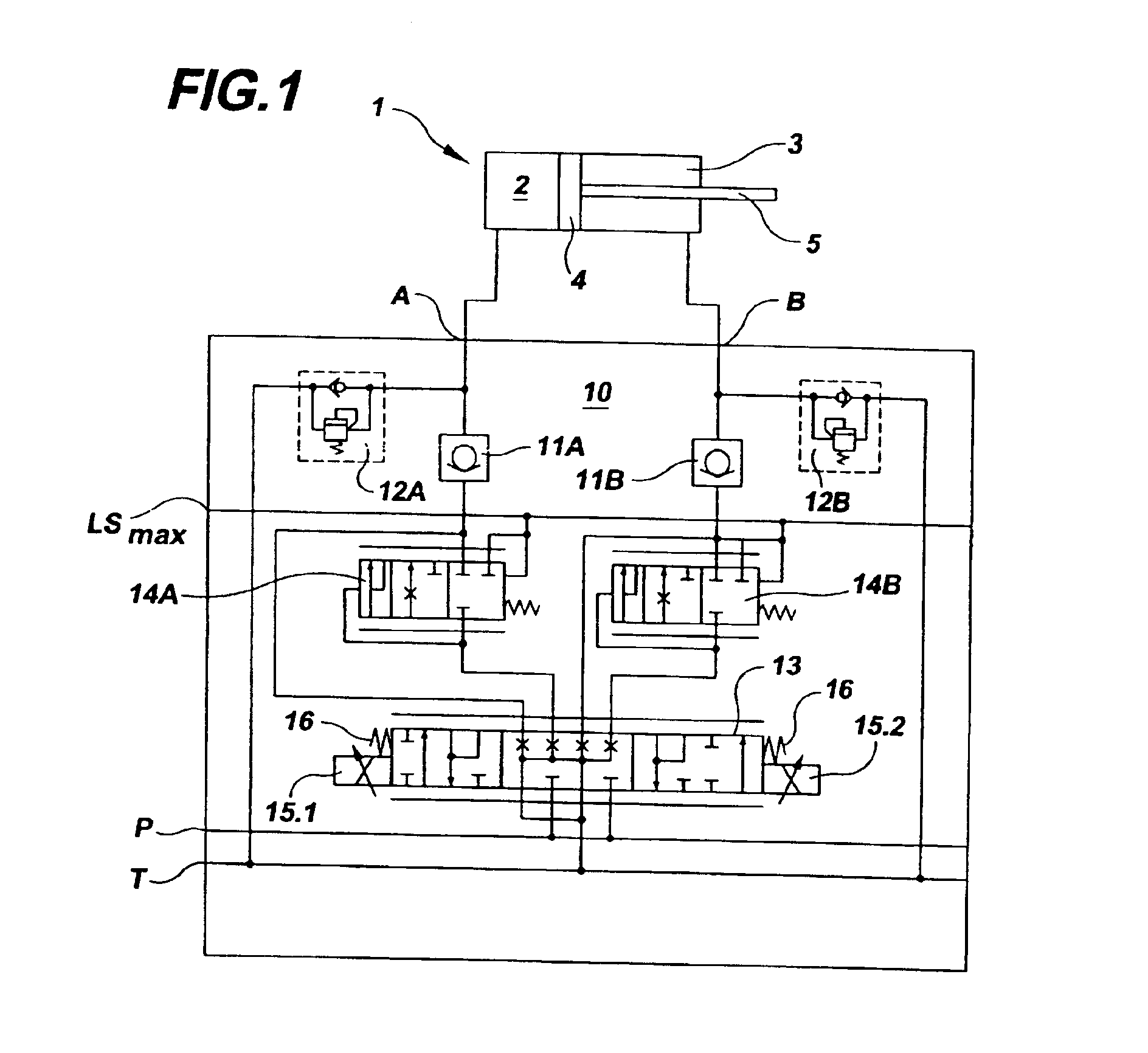
[0028]In FIG. 1, a differential cylinder 1 has a first pressure space 2 and a second pressure space 3 which are separated from one another by a piston 4. Fastened to the piston 4 is a tappet 5 which transmits the movement of the piston 4 to an implement, not illustrated. The differential cylinder 1 is in this case only one possible example of use. Instead, for example, an oil motor may also be used.
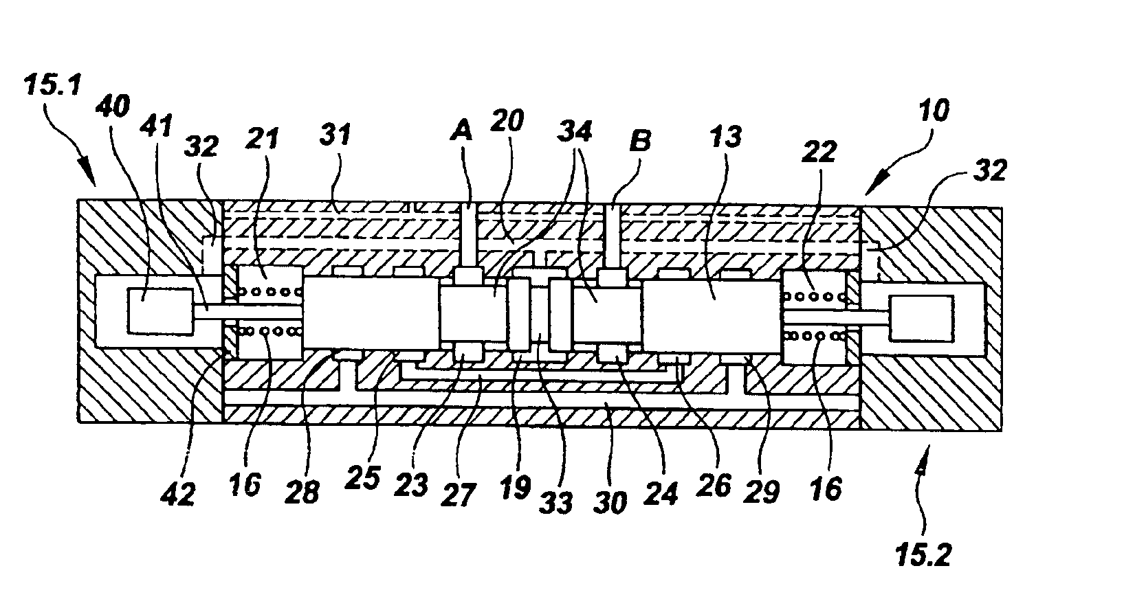
[0029]The differential cylinder 4 is activated by a directional valve 10 which is designed according to the invention. In a known way, the directional valve 10 has working connections A and B, the first working connection A being connected to the first pressure space 2 and the second working connection B to the second pressure space 3 of the differential cylinder 1.
[0030]The directional valve 10 consists of a number of components and its construction is outlined below. A releasable nonreturn valve 11A lies at the working connection A and a releasable non-return valve 11B lies at the worki...
PUM
 Abstract
Description
Claims
Application Information