Hand tool machine comprising a vibration-dampened handle

Inactive Publication Date: 2006-09-05
ROBERT BOSCH GMBH
View PDF12 Cites 53 Cited by
  • Summary
  • Abstract
  • Description
  • Claims
  • Application Information

AI Technical Summary

Benefits of technology

[0005]The stated object is obtained 1 by the fact that the handle is coupled with the machine housing via two or more parallel levers situated nearly perpendicular to the longitudinal axis of the hand power tool, whereby the levers are hinge-mounted on the machine housing

Problems solved by technology

In the case of hand power tools having a striking drive in particular, e.g., drilling hammers, chipping hammers, and the like, extremely strong vibrations are produced in the machine that are transferred to the handle of the machine and are

Method used


Image

  • Hand tool machine comprising a vibration-dampened handle
  • Hand tool machine comprising a vibration-dampened handle
  • Hand tool machine comprising a vibration-dampened handle

Examples


Embodiment Construction

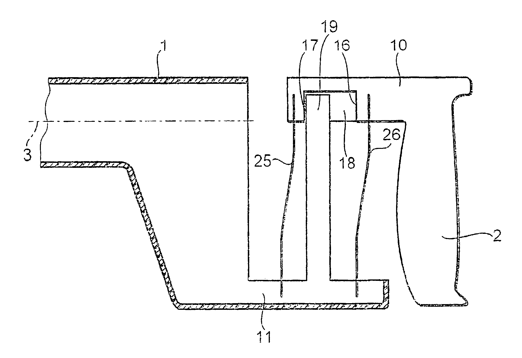
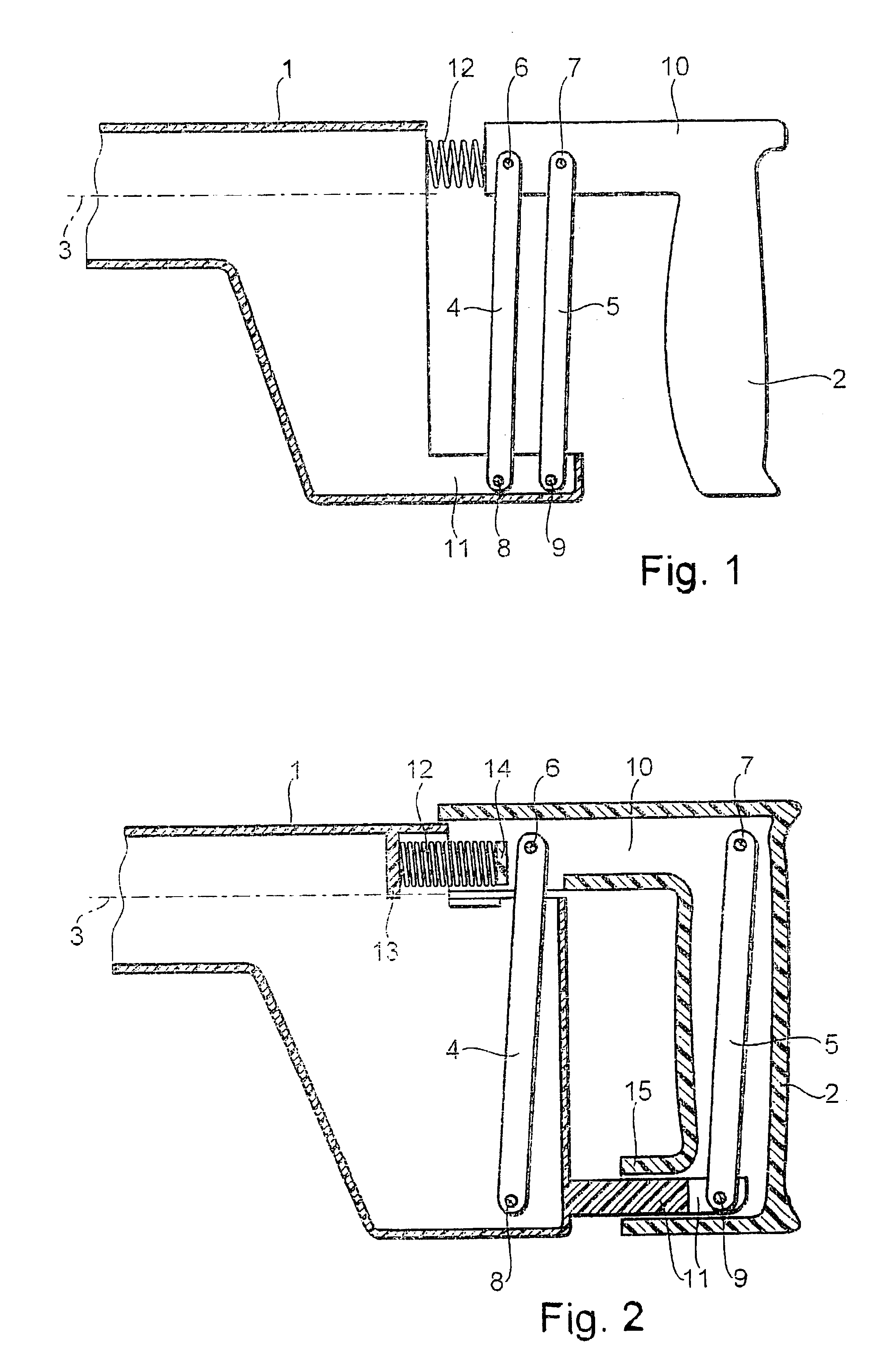
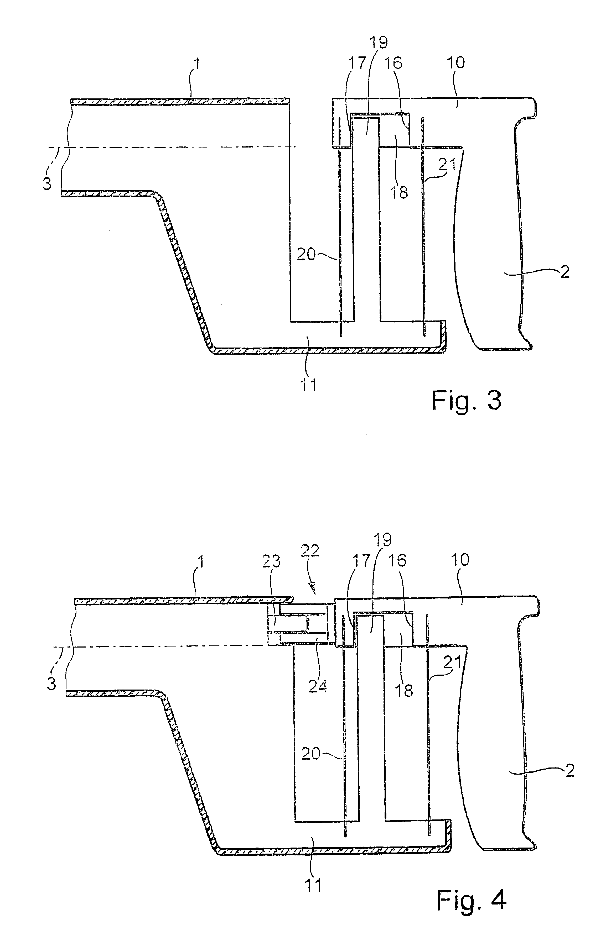
[0017]A hand power tool, e.g., a drilling hammer or a chipping hammer or the like, is shown in FIG. 1. The hand power tool is composed of a machine housing 1 in which the machine drive is located, and a handle 2 coupled with the machine housing 1.

[0018]The handle 2 is coupled with the machine housing 1 via a parallel rocker arm. This parallel rocker arm is composed of two levers 4 and 5 situated parallel with one another and extending nearly perpendicular to the longitudinal axis 3 of the machine. Instead of the two levers 4 and 5 shown in the drawing, more than just two parallel levers can also be used. The levers 4 and 5 are hinge-mounted on the handle 2 on the one hand and on the machine housing 1 on the other hand in such a fashion that the handle 2 can perform a relative motion in relation to the machine housing 1 nearly exclusively in the direction of the longitudinal axis 3.

[0019]So that only one absolutely minimal portion of the tilting motion can occur between the handle 2 ...


PUM

PropertyMeasurementUnit
Forceaaaaaaaaaa

Abstract

A coupling between the handle (2) and the machine housing (1) of a hand power tool having the greatest possible vibration damping is produced by the fact that the handle (2) is coupled with the machine housing (1) via two or more parallel levers (4, 5) situated nearly perpendicular to the longitudinal axis (3) of the hand power tool, whereby the levers (4, 5) are hinge-mounted on the machine housing (1) on the one hand and on the handle (2) on the other hand.

Description

BACKGROUND OF THE INVENTION[0001]The present invention concerns a hand power tool with vibration-damped handle that is coupled with the machine housing using damping means.[0002]In the case of hand power tools having a striking drive in particular, e.g., drilling hammers, chipping hammers, and the like, extremely strong vibrations are produced in the machine that are transferred to the handle of the machine and are not only uncomfortable for the operator, but they can be harmful as well. Measures are made known in DE 195 03 526 A1 or U.S. Pat. No. 5,697,456, for example, for damping the handle of a hand power tool against vibrations. These measures are based on the fact, for example, that the handle is joined at one end with the machine housing via a damping spring or a spring system, and that the handle is joined on the opposite end with the machine housing by means of a pivot joint. It is also proposed in DE 195 03 526 A1 that the handle is joined at both ends with the machine hou...

Claims


Application Information

Patent Timeline
IPC IPC(8): B25D17/04B25F5/00B25F5/02
CPCB25D17/043B25F5/006B25D2250/381
Inventor MEIXNER, GERHARDJEANNIN, PIERREMAILLARD, PATRICK
Owner ROBERT BOSCH GMBH
Why Eureka
Try Eureka