Mechanical device to encode magnetic cards

Inactive Publication Date: 2006-09-05
SEDLEY BRUCE S
View PDF7 Cites 1 Cited by
  • Summary
  • Abstract
  • Description
  • Claims
  • Application Information

AI Technical Summary

Benefits of technology

[0009]It is a purpose of this invention to eliminate the need for the ele

Problems solved by technology

When the electric encoding device is battery operated there has always been the problem that when the batteries become weak so does the resulting magnetic area on the key, and t

Method used


Image

  • Mechanical device to encode magnetic cards
  • Mechanical device to encode magnetic cards
  • Mechanical device to encode magnetic cards

Examples


Embodiment Construction

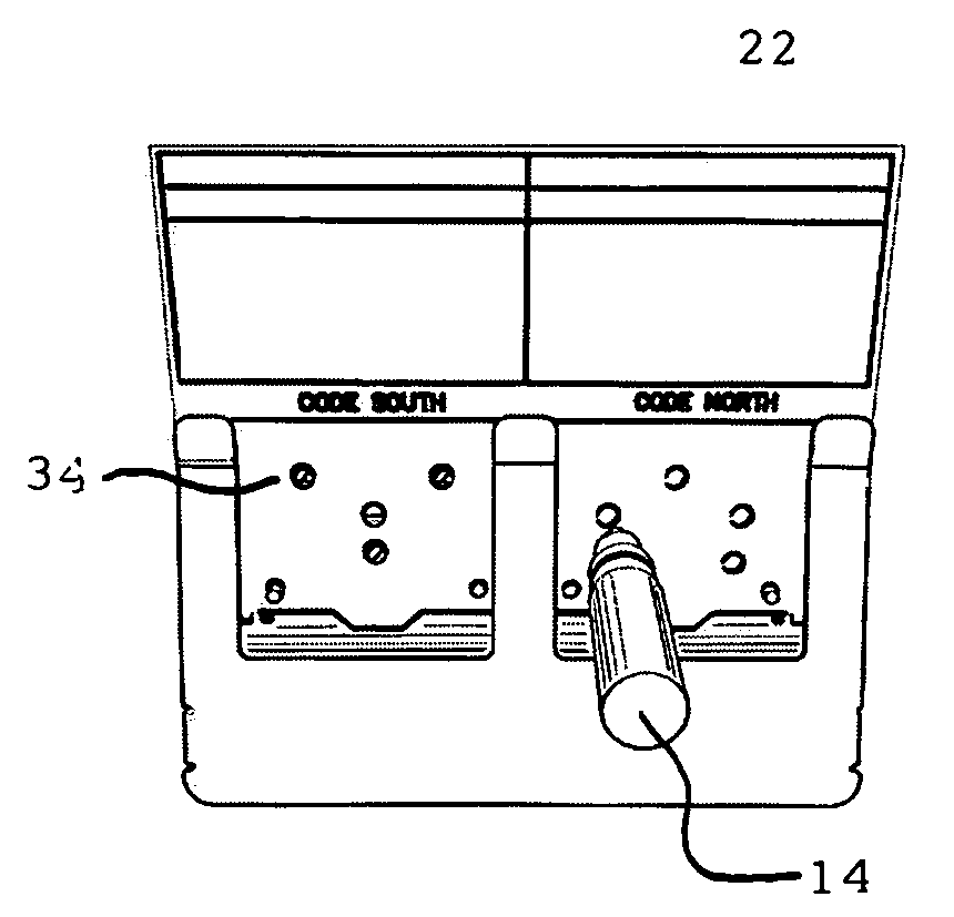
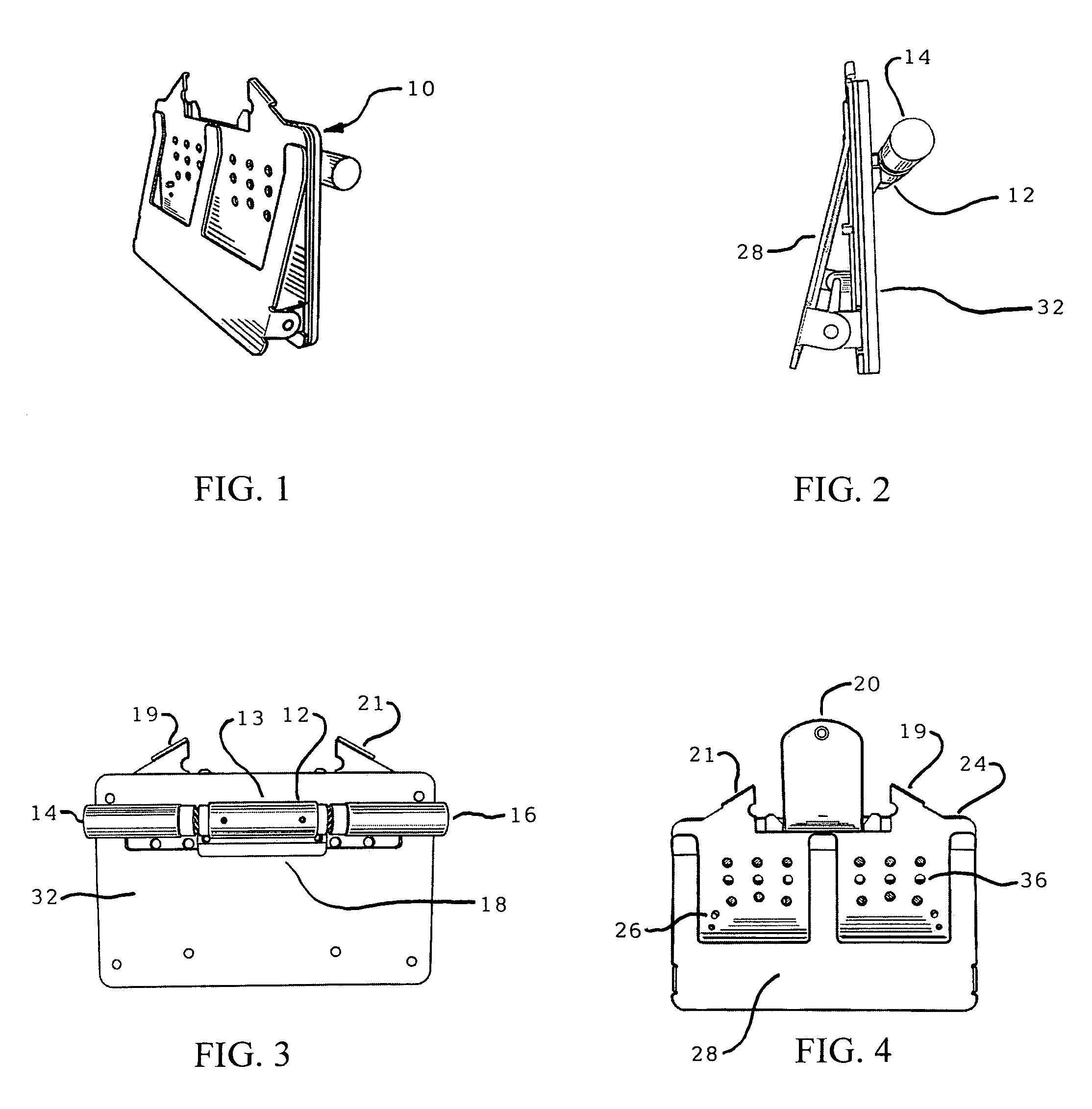
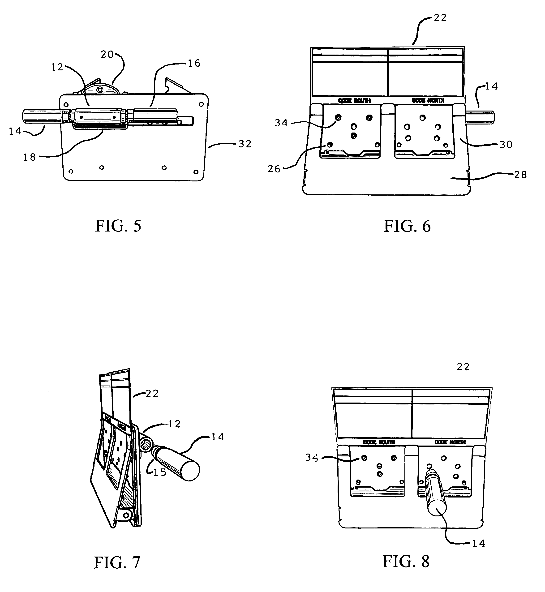
[0038]First referring primarily to FIGS. 1–4, the code fixture device 10 includes a tool holder in the form of a hollow tube 12 for the two permanent magnet encoding tools 14, 16, which has been fitted with a permanent magnet 13 in its center so when the correct tool 14 or 16 is inserted in the tube 12 it is attracted to the internal magnet 13 and is retained in position. If the wrong tool 14 or 16 is inserted it is repelled by the internal magnet 13. In this manner it is only possible to place the tools 14, 16 in their respective tube 12 ends after use and for storage. The internal magnet 13 also serves as a “keeper” for the tools 14, 16 and tends to retain their magnetic strength.

[0039]The tube 12 with inserted tools 14, 16 is fixed to the sliding card holder section 18 of the code fixture 10 into which the key 20 is inserted for the purpose of encoding. Pulling or pushing horizontally on the tube 12 moves the slider 18 to either side of the code fixture 10 for the purpose of posi...


PUM


Abstract

A fixture for magnetically coding a card key includes a front plate with areas for North and South magnetic polarity coding each with a number of holes, an optional code template having a lesser number of holes corresponding to selected holes in the front plate and attachable to the front plate, and North and South permanent magnet encoding tools sized to be inserted into the holes in the code template and front plate. The device further includes a card key holder preferably coupled to a tool holder and slidably connected to the fixture for placing the card key proximate the North or South area of the front plate and positioning the appropriate encoding tool for easy access. The device provides for convenient, accurate and error-free magnetic coding of card keys.

Description

CROSS REFERENCE TO RELATED DOCUMENTS[0001]This application is based on provisional application Ser. No. 60 / 700,032 filed Jul. 16, 2005.BACKGROUND OF THE INVENTION[0002]Magnetic key cards such as described in Sedley U.S. Pat. No. 4,077,242 “Metal Magnetic Key” require a substantial amount of magnetic energy to encode discrete magnetic areas in specific locations to operate card locks that utilize magnetic pin tumblers to form the code of the lock, for example, the “Magnetic Key Operated Door Lock” as described in Sedley U.S. Pat. No. 4,133,194. The method that has been utilized for many years is an electronic device such as described in Sedley U.S. Pat. No. 4,128,851 “Hand Held Magnetic Encoder.”[0003]Developments of new permanent magnetic materials in recent years, such as Neodymium which has very strong magnetic properties, have been found to be of sufficient strength so that by forming a magnet of the proper size and simply touching it to the said magnetic key creates a magnetic a...

Claims


Application Information

Patent Timeline
IPC IPC(8): G06K7/00
CPCE05B19/00G06K1/125E05B47/0043
Inventor SEDLEY, BRUCE S.
Owner SEDLEY BRUCE S
Why Eureka
Try Eureka