Hole saw assembly

a technology of hole saw and assembly, which is applied in the direction of sleeves/socket joints, boring/drilling components, fastening means, etc., can solve the problems of tight plugging, difficult removal of plugs, and considerable force to be used to remove plugs

Inactive Publication Date: 2006-09-05
KEIGHTLEY KYM JOHN
View PDF35 Cites 76 Cited by
  • Summary
  • Abstract
  • Description
  • Claims
  • Application Information

AI Technical Summary

Benefits of technology

[0031]An advantage of such an arrangement is that a hole saw may be rapidly removed and re-attached to a mandrel without the use of threads and without the use of a tool. This is particularly advantageous when the hole saw becomes clogged and needs to be cleared or when the hole saw is interchanged with a hole saw of a different size.
[0032]Still a further advantage is that by utilising a boss, commonly available hole-saws may be used with the mandrel.

Problems solved by technology

A universal problem when using hole-saws is that when a hole has been drilled through a material, the material that has been cut out, commonly referred to as the plug, remains embedded within the hole-saw and needs to be removed.
Typically the plug is jammed tightly within the hole-saw and considerable force needs to be used to remove the plug using a sharp instrument, such as a screwdriver.
However, some materials, such as plastic, possess material characteristics that make their removal difficult.
Whilst some of these have been found to work well, they are generally mechanically quite complicated.
Further, the hole-saw is a dedicated size being limited to a pre-determined diameter and to drill larger size holes requires the use of a whole new hole-saw assembly.
A still further limitation of existing hole-saw assemblies is that they can at any one time only accommodate one hole-saw and do not enable the simultaneous use of two different sized hole-saws.

Method used


Image

  • Hole saw assembly
  • Hole saw assembly
  • Hole saw assembly

Examples


Embodiment Construction

[0047]The following detailed description of the invention refers to the accompanying drawings. Although the description includes exemplary embodiments, other embodiments are possible, and changes may be made to the embodiments described without departing from the spirit and scope of the invention. Wherever possible, the same reference numbers will be used throughout the drawings and the following description to refer to the same and like parts.

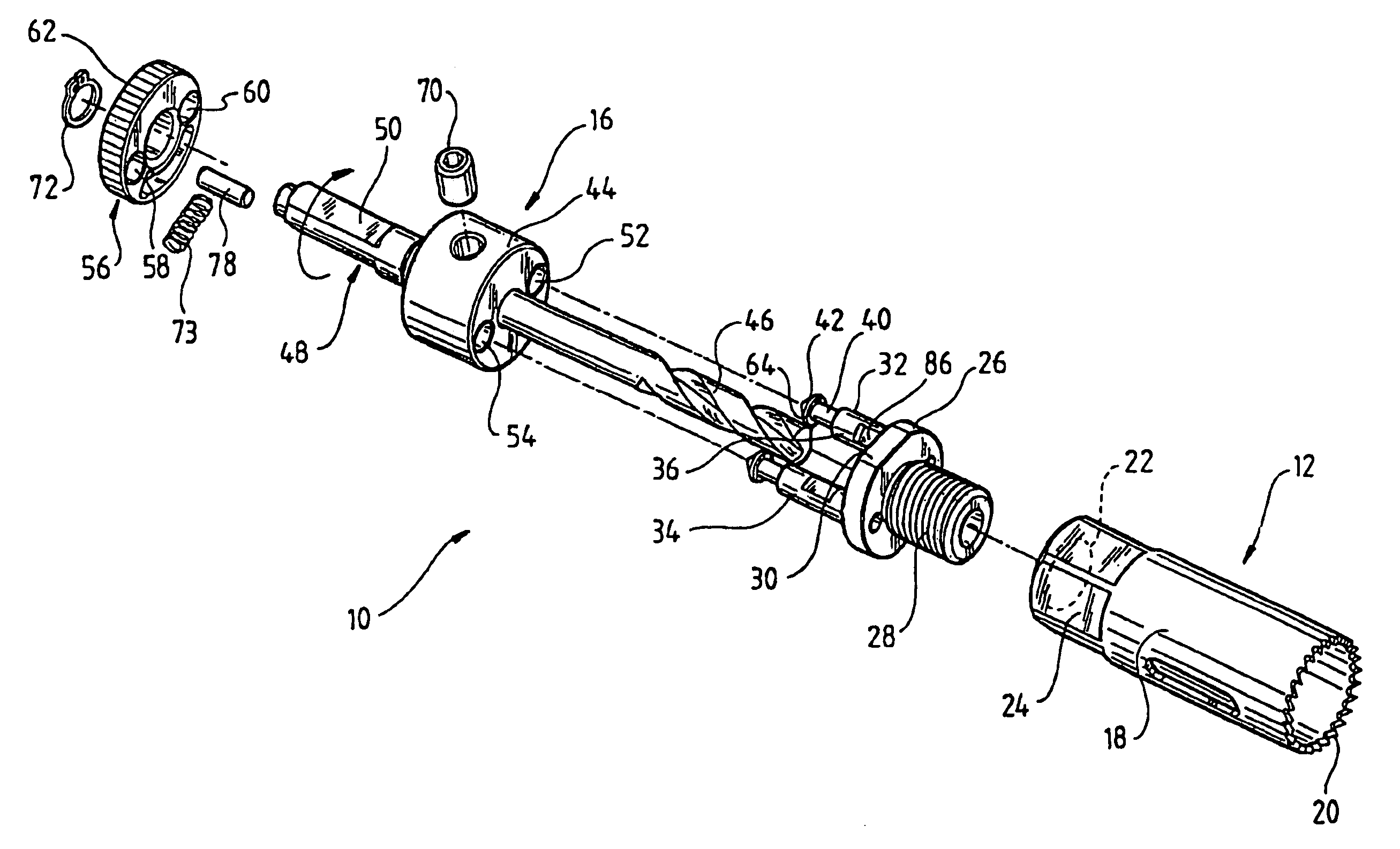
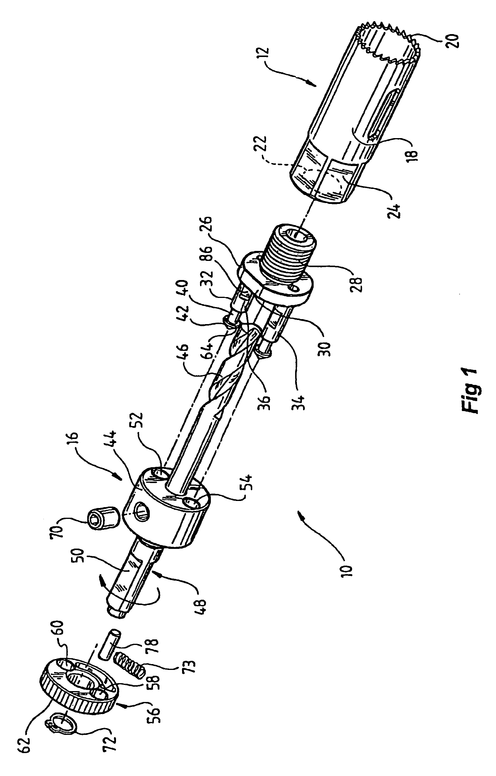
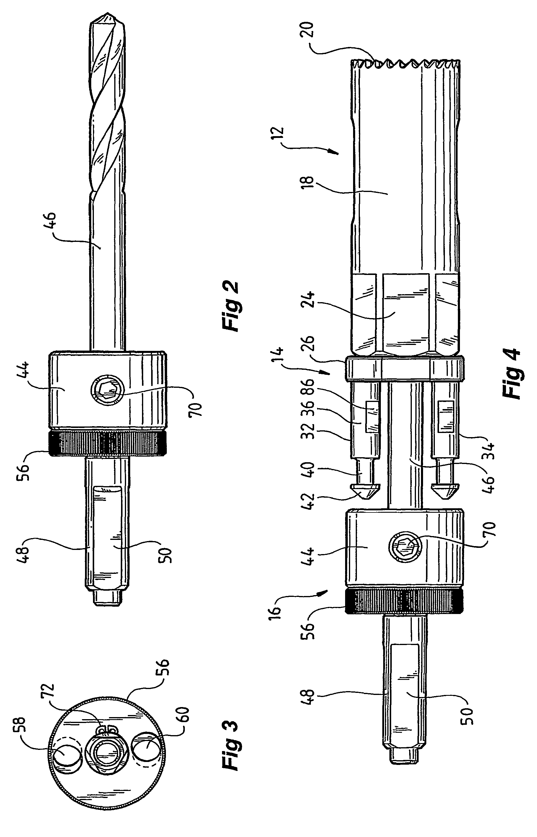
[0048]Referring to FIGS. 1 to 5 there is shown a hole-saw assembly 10 including a hole-saw 12, base 14, and mandrel 16.

[0049]The hole-saw 12 includes a cylindrical body 18 having cutting teeth 20 at one end thereof. At the opposite end the hole-saw 12 includes a threaded bore 22 (with inner threads), the outer surface of the hole-saw body 18 adjacent the bore 22 including circumferentially disposed shoulders 24 to enable a tool (not shown) such as a wrench to engage the hole-saw 12 for rotational movement thereof.

[0050]The base 14 includes dis...


PUM

PropertyMeasurementUnit
diameteraaaaaaaaaa
thicknessaaaaaaaaaa
longitudinal movementaaaaaaaaaa

Abstract

A hole-saw assembly including a hole-saw having at one end a plurality of cutting teeth and at the other end two shafts. The assembly includes a mandrel coaxially aligned with said hole-saw and including a body having two bores therethrough coaxially aligned with said shafts. An annulus located on top of the body is coaxially aligned with said mandrel and hole saw and includes two holes, the annulus rotatable around its longitudinal axis from a first to a second position. In the first position the annulus holes are aligned with the bores and shafts allowing the shafts to be freely insertable and removable and in the second position the holes are misaligned to lock the shafts to the annulus. Such an arrangement allows the hole-saw and the mandrel to be easily and quickly mountable and demountable.

Description

BACKGROUND OF THE INVENTION[0001]The present invention relates to an improved hole-saw assembly or arrangement and in particular to a hole-saw with a base that is easily demountable and mountable from a mandrel engageable by a drill.[0002]Hole-saws are a very widely used tool for many applications. Typically a hole-saw includes a flat solid base that is locked by a drill, the base providing support for the hole-saw. Some bases include multiple diameter grooves adapted to accommodate hole-saws of different diameters. Yet others are single sized hole-saws.[0003]A universal problem when using hole-saws is that when a hole has been drilled through a material, the material that has been cut out, commonly referred to as the plug, remains embedded within the hole-saw and needs to be removed. Typically the plug is jammed tightly within the hole-saw and considerable force needs to be used to remove the plug using a sharp instrument, such as a screwdriver. However, some materials, such as pla...

Claims


Application Information

Patent Timeline
Patent Type & Authority Patents(United States)
IPC IPC(8): B23B51/04B27B33/18
CPCB23B31/11B23B51/0426B23B51/0473B27B5/12B27B5/32B23B31/113Y10T408/895B23B2270/14Y10T403/599Y10T403/7005Y10T403/7007Y10T408/95Y10T403/57Y10T403/75Y10T403/7009Y10T403/59Y10T403/7039Y10T279/3418Y10T83/9461Y10T83/9457F16B2200/10
Inventor KEIGHTLEY, KYM JOHN
Owner KEIGHTLEY KYM JOHN
Why Eureka
Try Eureka