Ballast with end-of-lamp-life protection circuit

a protection circuit and ballast technology, applied in the direction of electrical equipment, instruments, light sources, etc., can solve the problems of increased power dissipation in the cathode, potentially serious safety hazards, and significant increase in the temperature of the lamp in the area of the cathod

Inactive Publication Date: 2006-09-05
OSRAM SYLVANIA INC
View PDF4 Cites 14 Cited by
  • Summary
  • Abstract
  • Description
  • Claims
  • Application Information

AI Technical Summary

Problems solved by technology

The increased voltage drop caused increased power dissipation in that cathode and a potentially significant increase in the temperature of the lamp in the area of that cathode.
The localized high temperatures that often occur in small diameter lamps during end-of-life conditions present a potentially serious safety hazard.

Method used


Image

  • Ballast with end-of-lamp-life protection circuit
  • Ballast with end-of-lamp-life protection circuit
  • Ballast with end-of-lamp-life protection circuit

Examples


Embodiment Construction

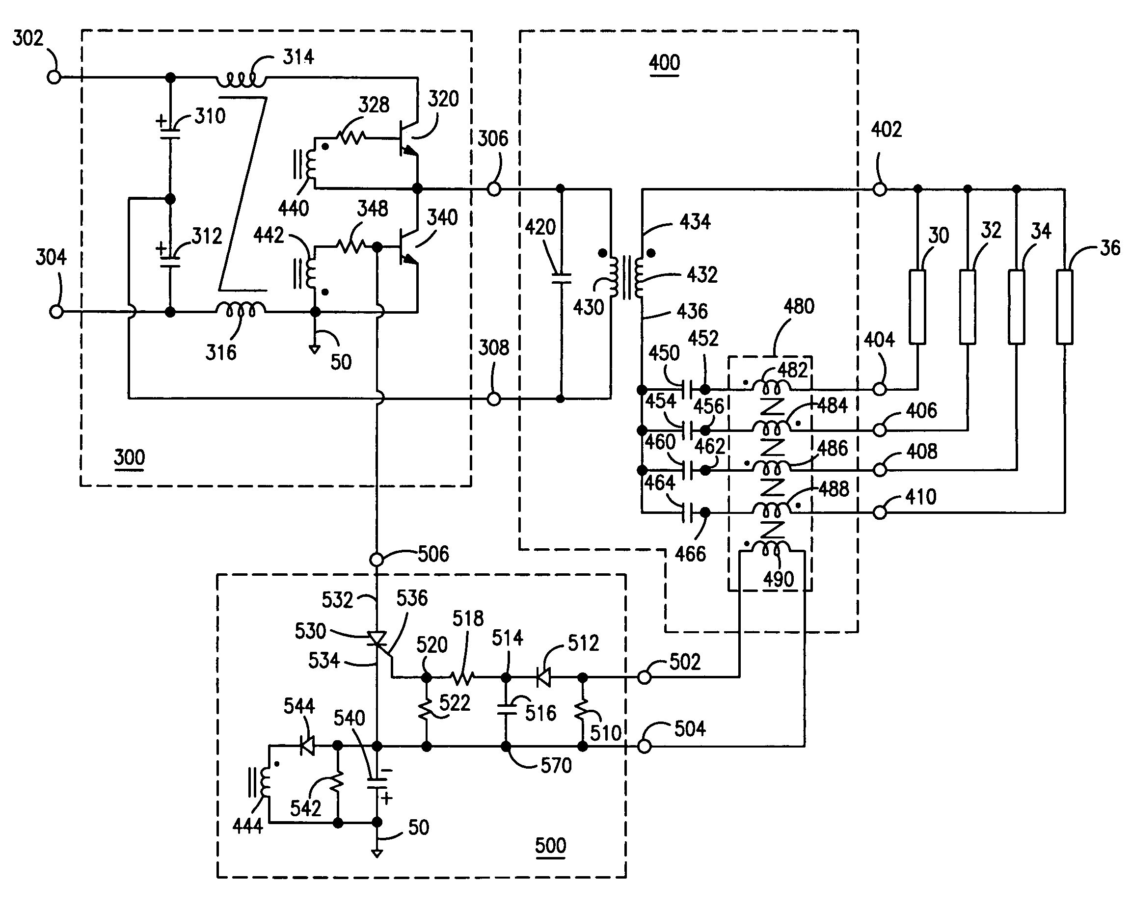
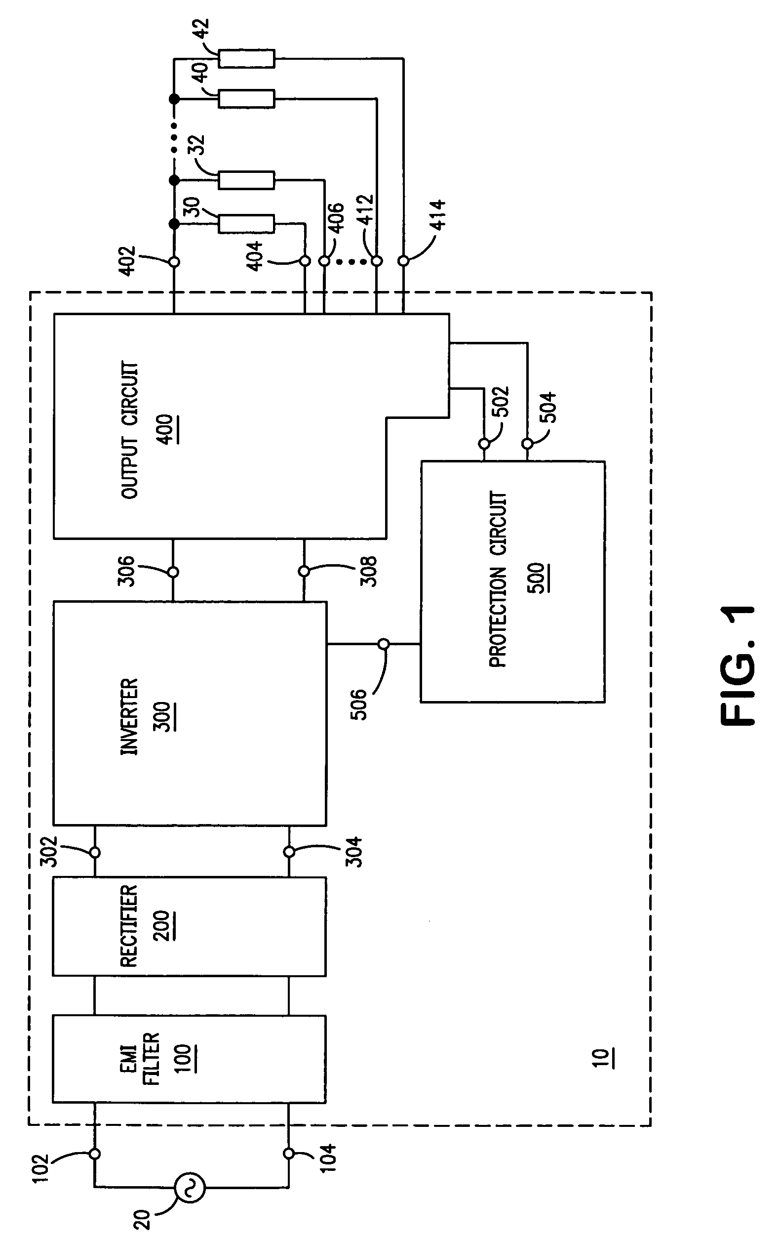
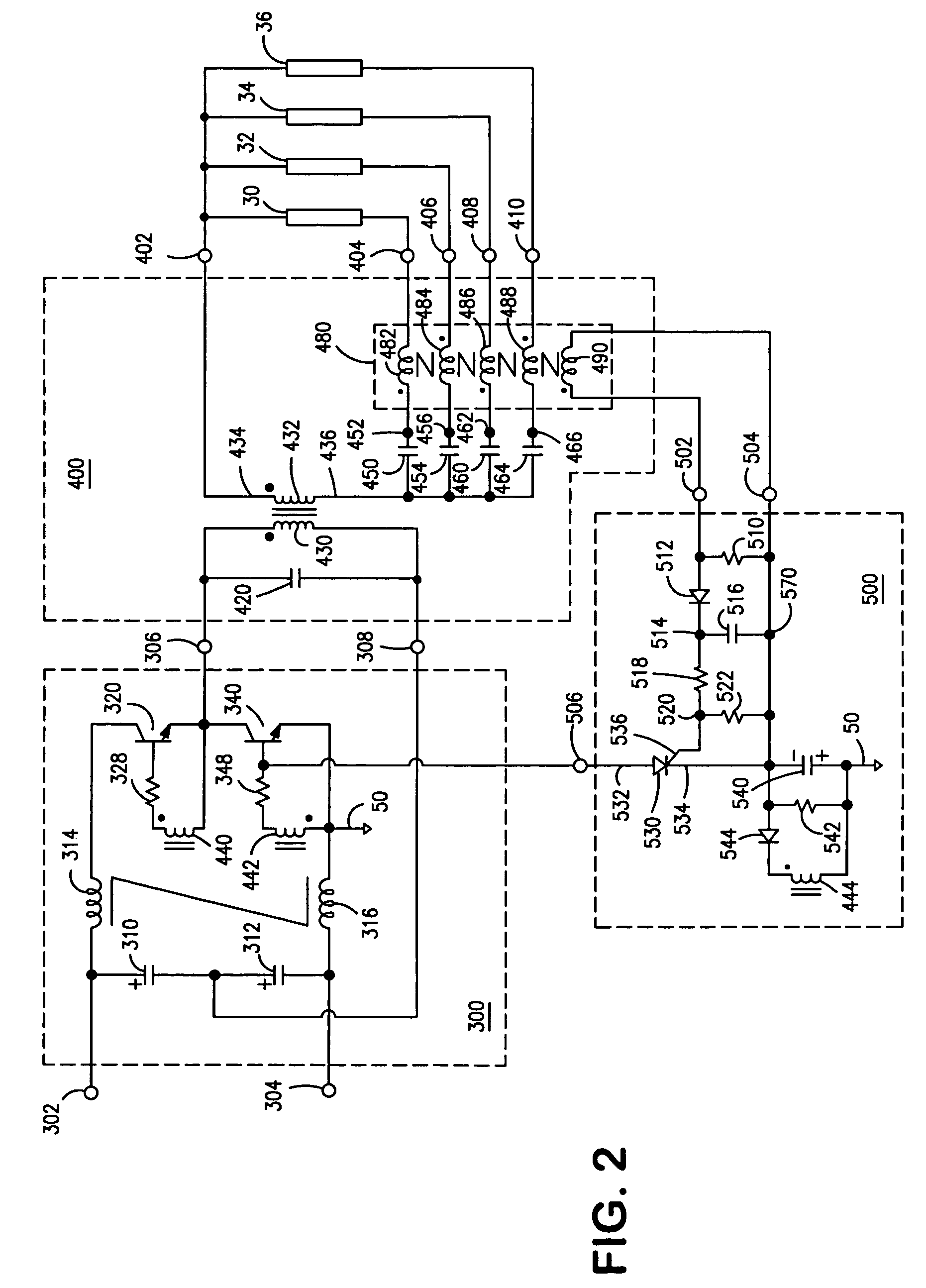
[0008]FIG. 1 describes an electronic ballast 10 for powering a lamp load that includes an even number (2N) of gas discharge lamps 30,32, . . . ,40,42. Ballast 10 comprises an electromagnetic interference (EMI) filter 100, a rectifier circuit 200, an inverter 300, an output circuit 400, and a protection circuit 500.

[0009]EMI filter 100 comprises input terminals 102,104 that are adapted to receive a conventional source of alternating current (AC) voltage, such as 120 volts (rms) at 60 hertz. Rectifier circuit 200 is coupled to EMI filter 100, and provides a substantially direct current (DC) voltage to inverter 200. EMI filter 100 and rectifier circuit 200 may be realized by any of a number of suitable arrangements that are well known to those skilled in the art. For example, rectifier circuit 200 may be realized by a combination of a full-wave diode bridge and a boost converter.

[0010]Inverter 300 comprises input terminals 302,304 and output terminals 306,308. During operation, inverte...


PUM


Abstract

An electronic ballast (10) for powering a lamp load comprising an even number of gas discharge lamps (30,32, . . . ,34,36) includes an inverter (300), an output circuit (400), and a protection circuit (500). During operation, protection circuit (500) disables the inverter (300) in response to an end-of-lamp-life condition that is characterized by a predetermined imbalance in the operating current provided to each of the even number of lamps. Preferably, the output circuit (400) includes a current-sensing transformer (480) for detecting the predetermined imbalance, and the protection circuit (500) includes a silicon-controlled rectifier (530) for disabling the inverter (300).

Description

FIELD OF THE INVENTION[0001]The present invention relates to the general subject of circuits for powering discharge lamps. More particularly, the present invention relates to a ballast for powering an even number of lamps that includes a circuit for protecting the ballast and lighting fixture in the event of an end-of-lamp-life condition.BACKGROUND OF THE INVENTION[0002]When a fluorescent lamp approaches the end of its operating life, the electrode emission capability of at least one of its cathodes decreases, accompanied by a corresponding increase in the voltage drop across that cathode. The increased voltage drop caused increased power dissipation in that cathode and a potentially significant increase in the temperature of the lamp in the area of that cathode. The increase in temperature is especially pronounced in small diameter lamps (such as T5 lamps) because those lamps have a smaller surface area and a larger operating current in comparison with larger diameter lamps (such a...

Claims


Application Information

Patent Timeline
Patent Type & Authority Patents(United States)
IPC IPC(8): H05B41/16H05B37/02H05B41/285
CPCH05B41/2855
Inventor TRESTMAN, GRIGORIY A.PARISELLA, JOSEPH L.
Owner OSRAM SYLVANIA INC
Why Eureka
Try Eureka