Timepiece equipped with calendar mechanism including first and second date indicators

a technology of calendar mechanism and timepiece, which is applied in the direction of mechanical clocks, instruments, and horology, can solve the problems of large area large structure of the drive mechanism, and large space occupied by the drive mechanism, and achieves compact design, simple drive mechanism, and wide latitude in design.

Inactive Publication Date: 2006-09-05
SEIKO INSTR INC
View PDF13 Cites 26 Cited by
  • Summary
  • Abstract
  • Description
  • Claims
  • Application Information

AI Technical Summary

Benefits of technology

[0009]It is an object of the present invention to provide a calendar mechanism-equipped timepiece which includes first and second date indicators, has a simple drive mechanism for driving the first and second date indicators, and is designed compactly. Furthermore, it is another object of the present invention to provide a calendar mechanism-equipped timepiece of the present invention which offers wide latitude in designing the calendar correction mechanism.
[0010]The present invention can achieve a timepiece equipped with a calendar mechanism including two date indicators, the timepiece comprising a drive mechanism for driving the timepiece equipped with the calendar mechanism, time display wheels for displaying time information by being rotated by operation of the drive mechanism, a first date indicator for displaying the ones digit of the date, a second date indicator for displaying the tens digit of the date, and a program gear designed to be capable of intermittently rotating the first and second date indicators based on the operation of the drive mechanism. The center axis of rotation of the time display wheels is located inside a center hole in the program gear while the time display wheels are rotatable. Information about the date or day can be displayed by means of one of first day characters provided on the first date indicator and one of second day characters provided on the second date indicator, the first and second date indicators being placed in position adjacently to each other. Because of this structure, a calendar mechanism-equipped timepiece in which the drive mechanism for driving the first and second date indicators has been easily and compactly constructed can be accomplished.
[0011]In the calendar mechanism-equipped timepiece of the present invention, the center axis of rotation of the program gear is preferably set coincident with the center axis of rotation of the time display wheels. Furthermore, in the calendar mechanism-equipped timepiece of the present invention, the program gear preferably includes a program date indicator designed to be rotated based on operation of the drive mechanism, a first program gear designed to be capable of rotating as a unit with the program date indicator and of intermittently rotating the first date indicator, and a second program gear designed to be capable of rotating as a unit with the program date indicator and of intermittently rotating the second date indicator. Because of this structure, a compactly constructed timepiece with calendar mechanism can be accomplished.
[0012]In the calendar mechanism-equipped timepiece of the present invention, the program date indicator can have 31 tooth portions for accepting operation of the drive mechanism. The first program gear can have 30 tooth portions for rotating the first date indicator. The second program gear can have 8 tooth portions for rotating the second date indicator. The first date indicator can have a first date character display surface bearing 10 digits “1”, “2”, “3”, “4”, “5”, “6”, “7”“8”, “9”, and “0”arrayed in this order in a peripheral direction. The second date indicator can have a second date character display surface bearing 8 digits “0”, “0”, “1”, “1”, “2”, “2”, “3”, and “3” arrayed in this order in the peripheral direction. Because of this structure, a calendar mechanism-equipped timepiece including a large calendar display which is easy to see can be accomplished.
[0013]In the calendar mechanism-equipped timepiece of the present invention, the program date indicator can have 31 tooth portions for accepting operation of the drive mechanism. The first program gear can have 30 tooth portions for rotating the first date indicator. The second program gear can have 4 tooth portions for rotating the second date indicator. The first date indicator can have a first date character display surface bearing 10 digits “1”, “2”, “3”, “4”, “5”, “6”, “7”, “8”, “9”, and “0” arrayed in this order in a peripheral direction. The second date indicator can have a second date character display surface bearing 8 digits “0”, “1”, “2”, “3”, “0”, “1”, “2”, and “3” arrayed in this order in the peripheral direction. Because of this structure, a calendar mechanism-equipped timepiece including a large calendar display which is easy to see can be accomplished.
[0014]The calendar mechanism-equipped timepiece of the present invention is provided with a day indicator intermediate driving wheel designed to be rotated based on operation of the drive mechanism and be arranged to overlap the program gear, a day indicator driving wheel designed to be rotated based on rotation of the day indicator intermediate driving wheel, and a day indicating driving pawl designed to be rotated based on rotation of the day indicator driving wheel. The program date indicator is preferably designed to be rotated based on rotation of the day indicator driving pawl. Because of this structure, a compactly constructed calendar mechanism-equipped timepiece can be accomplished. The calendar mechanism-equipped timepiece of the present invention preferably has a program date indicator jumper for correcting or resetting rotation of the program date indicator, a first date indicator jumper for correcting or resetting rotation of the first date indicator, and a second date indicator jumper for correcting or resetting rotation of the second date indicator. Because of this structure, the rotations of the program date indicator, first date indicator, and second date indicator can be corrected or reset at the same time and reliably.

Problems solved by technology

Therefore, the drive mechanism is complex in structure.
There is the problem that the drive mechanism occupies a large area.
Furthermore, timepieces with the prior art calendar mechanism have problems that the drive mechanism is complex and that wide latitude is not offered in designing the calendar correction mechanism.

Method used


Image

  • Timepiece equipped with calendar mechanism including first and second date indicators
  • Timepiece equipped with calendar mechanism including first and second date indicators
  • Timepiece equipped with calendar mechanism including first and second date indicators

Examples


first embodiment

(1) Structure of First Embodiment of Calendar Mechanism-Equipped Timepiece of the Present Invention

[0044]A first embodiment of the calendar mechanism-equipped timepiece of the present invention is first described. The first embodiment of the calendar mechanism-equipped timepiece of the present invention is an embodiment in which a timepiece equipped with a calendar mechanism is constructed with a mechanical timepiece having an automatic winding mechanism.

(1-1) Structure of Front Side of Movement

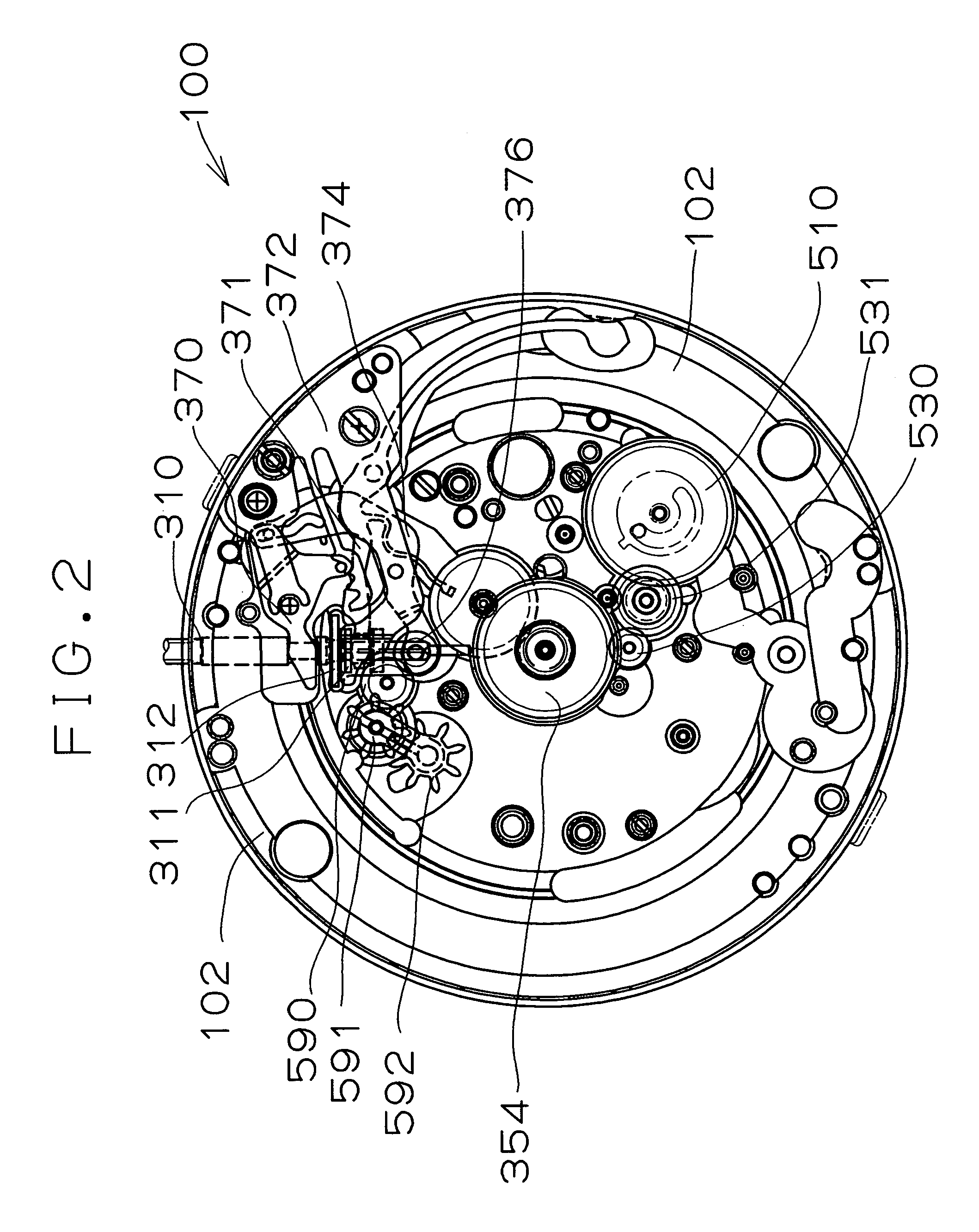
[0045]The structure of the front side (the side facing away from the dial of the bottomplate) of the movement is hereinafter described schematically. Referring to FIGS. 3–6, in the calendar mechanism-equipped timepiece of the present invention, the movement 100 has a bottom plate (or movement plate or main plate) 102 constituting a base plate of the movement 100. A stem 310 is rotatably mounted in a stem guide hole in the bottom plate 102. A dial 104 (indicated by phantom lines in FIGS. 3 and...

second embodiment

(2) Second Embodiment

[0081]A second embodiment of the calendar mechanism-equipped timepiece of the present invention is next described. The following description centers on the differences of the second embodiment of the calendar mechanism-equipped timepiece of the present invention from the first embodiment of the calendar mechanism-equipped timepiece of the present invention. Accordingly, in parts not specifically stated below, the description of the above-described first embodiment of the calendar mechanism-equipped timepiece of the present invention is applied here.

(2-1) Structure of the Second Embodiment

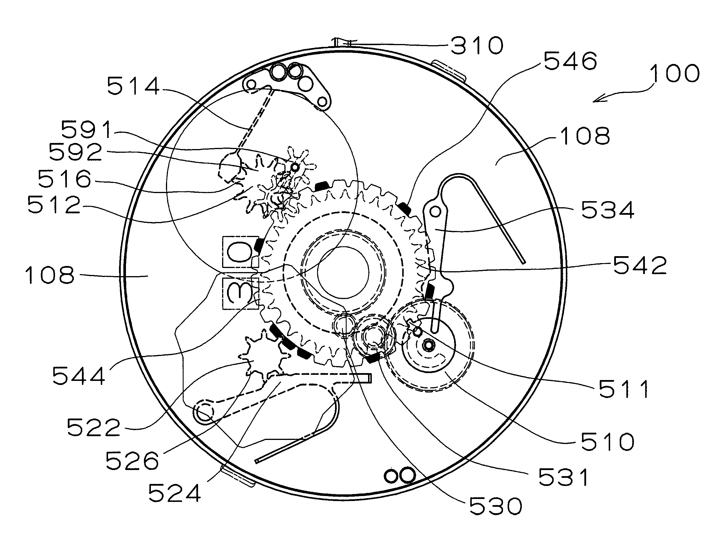
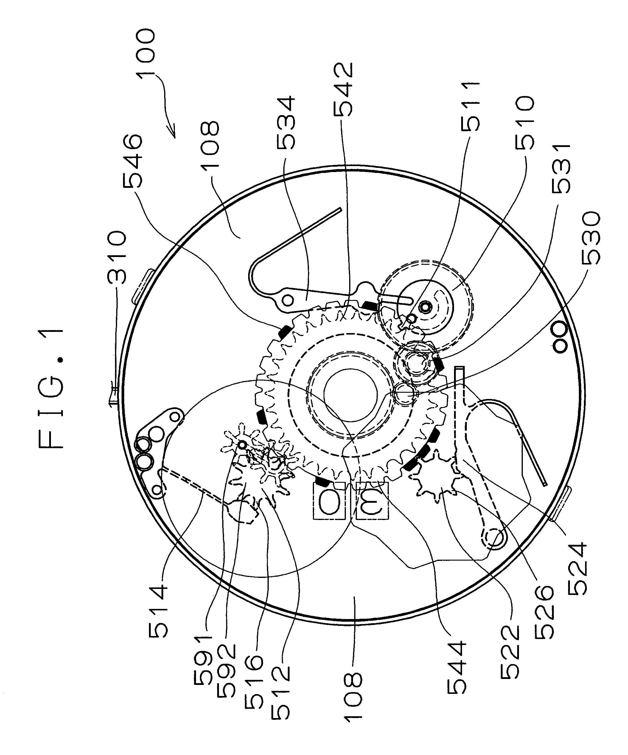
[0082]The structure of the second embodiment of the calendar mechanism-equipped timepiece of the present invention is hereinafter described. Referring to FIGS. 1–4 and 9–11, in a movement 190, a program wheel 560 includes a program date indicator 562, a first program gear 564, and a second program gear 566. The program date indicator 562 is identical in structure with the progra...

third embodiment

(3) Third Embodiment

[0092]The third embodiment of the calendar mechanism-equipped timepiece of the present invention is next described. The following description centers on the differences of the third embodiment of the calendar mechanism-equipped timepiece of the present invention from the first embodiment of the calendar mechanism-equipped timepiece of the present invention. Accordingly, in parts not specifically stated below, the description of the above-described first embodiment of the calendar mechanism-equipped timepiece of the present invention is applied here. The third embodiment of the calendar mechanism-equipped timepiece of the present invention is an analog electronic timepiece.

(3-1) Whole Structure of Movement

[0093]Referring to FIGS. 23 and 24, in the third embodiment of the calendar mechanism-equipped timepiece of the present invention, a movement 400 is constituted by an analog electronic timepiece. The movement 400 includes a bottom plate or main plate 402 forming ...


PUM


Abstract

A calendar mechanism-equipped timepiece having a compactly constructed drive mechanism for driving first and second date indicators is offered. A timepiece equipped with a calendar mechanism has a drive mechanism, time display wheels, a first date indicator for displaying the ones digit of the date, a second date indicator for displaying the tens digit of the date, and a program wheel capable of intermittently rotating the first date indicator and the second date indicator based on the operation of the drive mechanism. The center axis of rotation of the time display wheels is located within the center hole of the program wheel under the condition where the time display wheels are rotatable. The first and second date indicators are placed in position adjacently to each other. Information about the date can be displayed from a window in the dial by one of the first date characters on the first date indicator and one of the second date characters on the second date indicator.

Description

BACKGROUND OF THE INVENTION[0001]1. Field of the Invention[0002]The present invention relates to a timepiece equipped with a calendar mechanism including a first date indicator for displaying the ones digit of the date and a second date indicator for displaying the tens digit of the date. More particularly, the present invention relates to a timepiece equipped with a calendar mechanism and designed such that the center axis of rotation of the time display wheels is located inside the center hole in a program gear.[0003]2. Description of the Prior Art(1) Description of Terminology[0004]Generally, the mechanical body of a timepiece including the driver portion is referred to as the “movement”. A dial and hands are attached to the movement and put into a timepiece case, forming a completed product. This state is referred to as the “completed” state of the timepiece. A bottom plate or movement plate forms the base plate of the timepiece. The side of the bottom plate which faces the time...

Claims


Application Information

Patent Timeline
Patent Type & Authority Patents(United States)
IPC IPC(8): G04B19/20G04B19/24
CPCG04B19/25366G04B19/247
Inventor SUZUKI, SHIGEO
Owner SEIKO INSTR INC
Why Eureka
Try Eureka