Cooling roll, ribbon-shaped magnetic materials, magnetic powders and bonded magnets

a ribbon-shaped magnetic material and cooling roll technology, applied in the direction of magnetic materials, magnetic bodies, transportation and packaging, etc., can solve the problems of reducing the magnetic properties of bonded magnets formed from such magnetic powders, reducing the maximum magnetic energy product (bh)max, and reducing the oxidation risk of rare earth elements. , to achieve the effect of high maximum magnetic energy product (bhmax), excellent magnetic properties and high magnetic properties

Inactive Publication Date: 2005-05-17
SEIKO EPSON CORP
View PDF21 Cites 4 Cited by
  • Summary
  • Abstract
  • Description
  • Claims
  • Application Information

AI Technical Summary

Benefits of technology

[0148]In these three types of molding methods, the extrusion molding and the injection molding (in particular, the injection molding) have advantages in that the latitude of shape selection is broad and the productivity is high, for example. However, these molding methods require to ensure a sufficiently high fluidity of the compound in the molding machine in order to obtain satisfactory moldability. For this reason, in these methods it is not possible to increase the content of the magnetic powder, namely, it is not possible to make bonded magnets having high density, as compared with the case of the compaction molding method. In this invention, however, it is possible to obtain a high magnetic flux density as will be described later, so that excellent magnetic properties can be obtained even without making the bonded magnet high density. This advantage of the present invention can also be extended even in the case where bonded magnets are manufactured by the extrusion molding method or the injection molding method.
[0149]The content of the magnetic powder in the bonded magnet is not particularly limited, and it is normally determined by considering the kind of the molding method to be used and the compatibility of moldability and high magnetic properties. For example, it is preferred that the content is in the range of 75-99.5 wt %, and more preferably in the range of 85-97.5 wt %.
[0150]In particular, in the case of a bonded magnet manufactured by the compaction molding method, the content of the magnetic powder should preferably lie in the range of 90-99.5 wt %, and more preferably in the range of 93-98.5 wt %.
[0151]Further, in the case of a bonded magnet manufactured by the extrusion molding or the infection molding, the content of the magnetic powder should preferably lie in the range of 75-98 wt %, and more preferably in the range of 85-97 wt %.
[0152]The density ρ of the bonded magnet is determined by factors such as the specific gravity of the magnetic powder contained in the bonded magnet and the content of the magnetic powder, and the void ratio (porosity) of the bonded magnet and the like. In the bonded magnets according to this invention, the density ρ is not particularly limited to a specific value, but it is preferable to be in the range of 4.5-6.6 Mg / m3, and more preferably in the range of 5.5-6.4 Mg / m3.
[0153]In this invention, since the remanent magnetic fluxdensity and the coercive force of the magnetic powder are high, the bonded magnet formed from the magnetic powder provides excellent magnetic properties (especially, high maximum magnetic energy product (BH)max) even when the content of the magnetic powder is relatively low. In this regard, it goes without saying that it is possible to obtain the excellent magnetic properties in the case where the content of the magnetic powder is high.

Problems solved by technology

The rare-earth elements are liable to oxidize.
As a result, at portions of the melt spun ribbon where such dimples are formed, the crystal grain size of the alloy becomes coarse, which results in lowered magnetic properties.
Therefore, bonded magnet formed from such magnetic powder can have only poor magnetic properties, and corrosion resistance thereof is also low.

Method used


Image

  • Cooling roll, ribbon-shaped magnetic materials, magnetic powders and bonded magnets
  • Cooling roll, ribbon-shaped magnetic materials, magnetic powders and bonded magnets
  • Cooling roll, ribbon-shaped magnetic materials, magnetic powders and bonded magnets

Examples


example 1

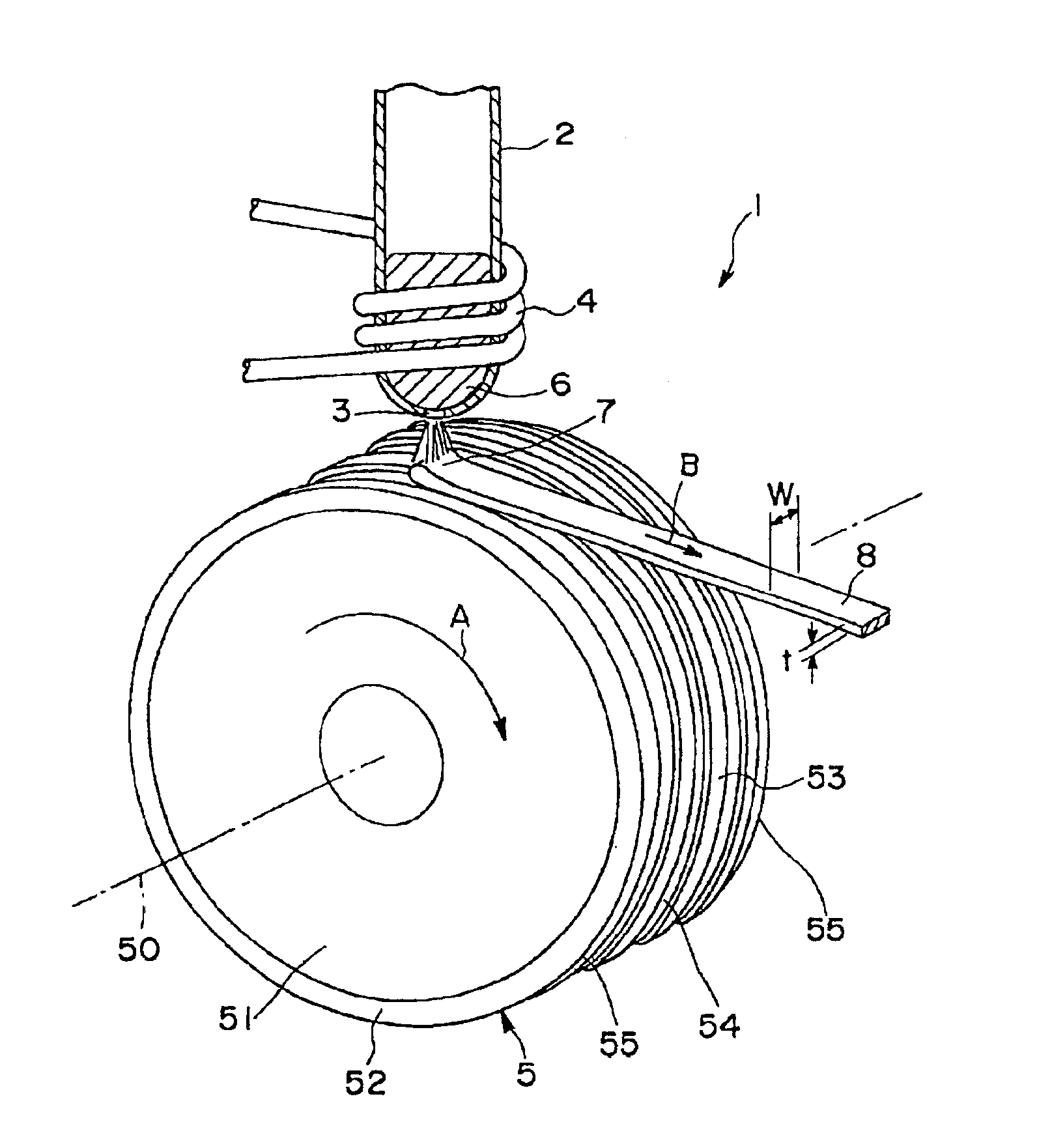
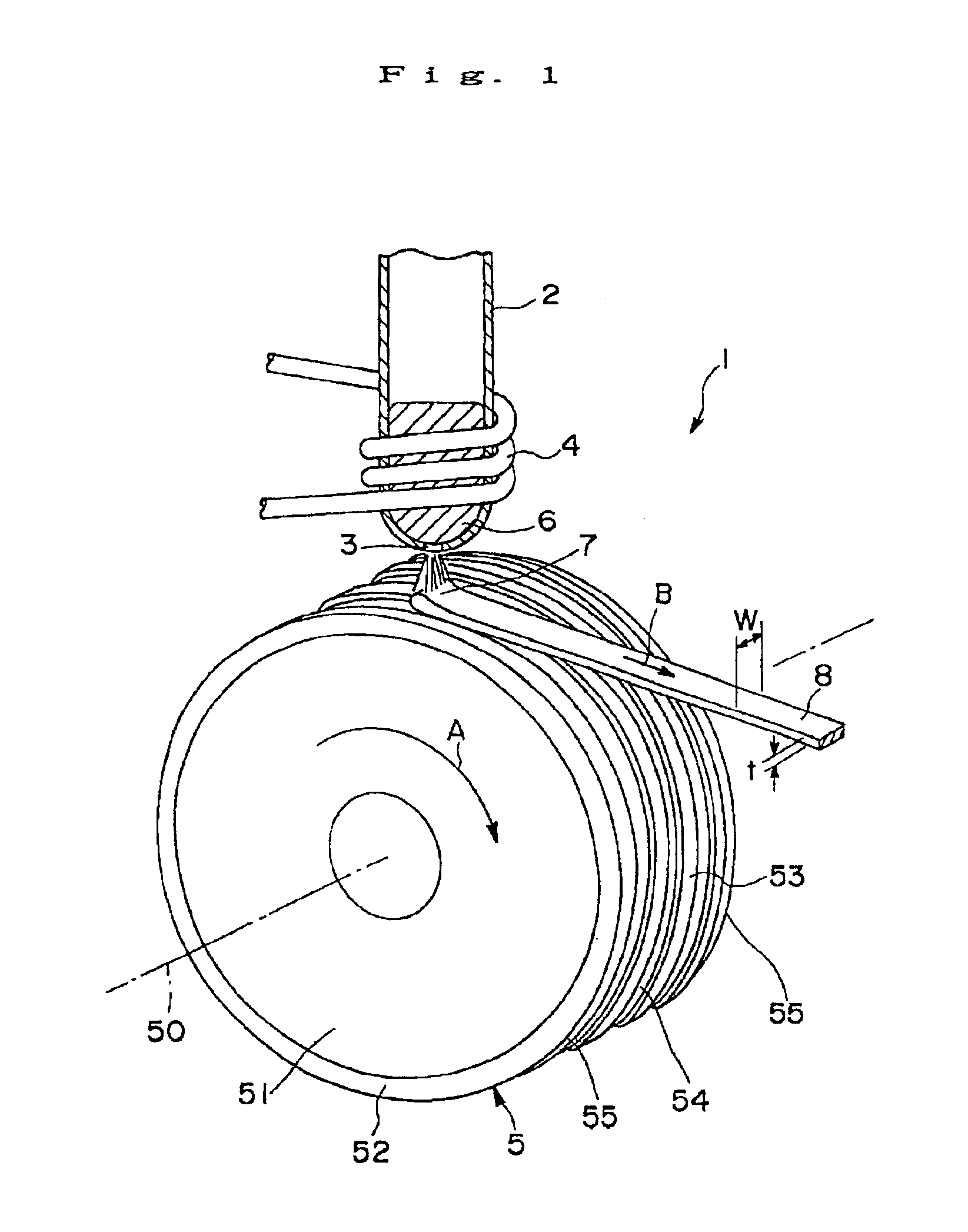
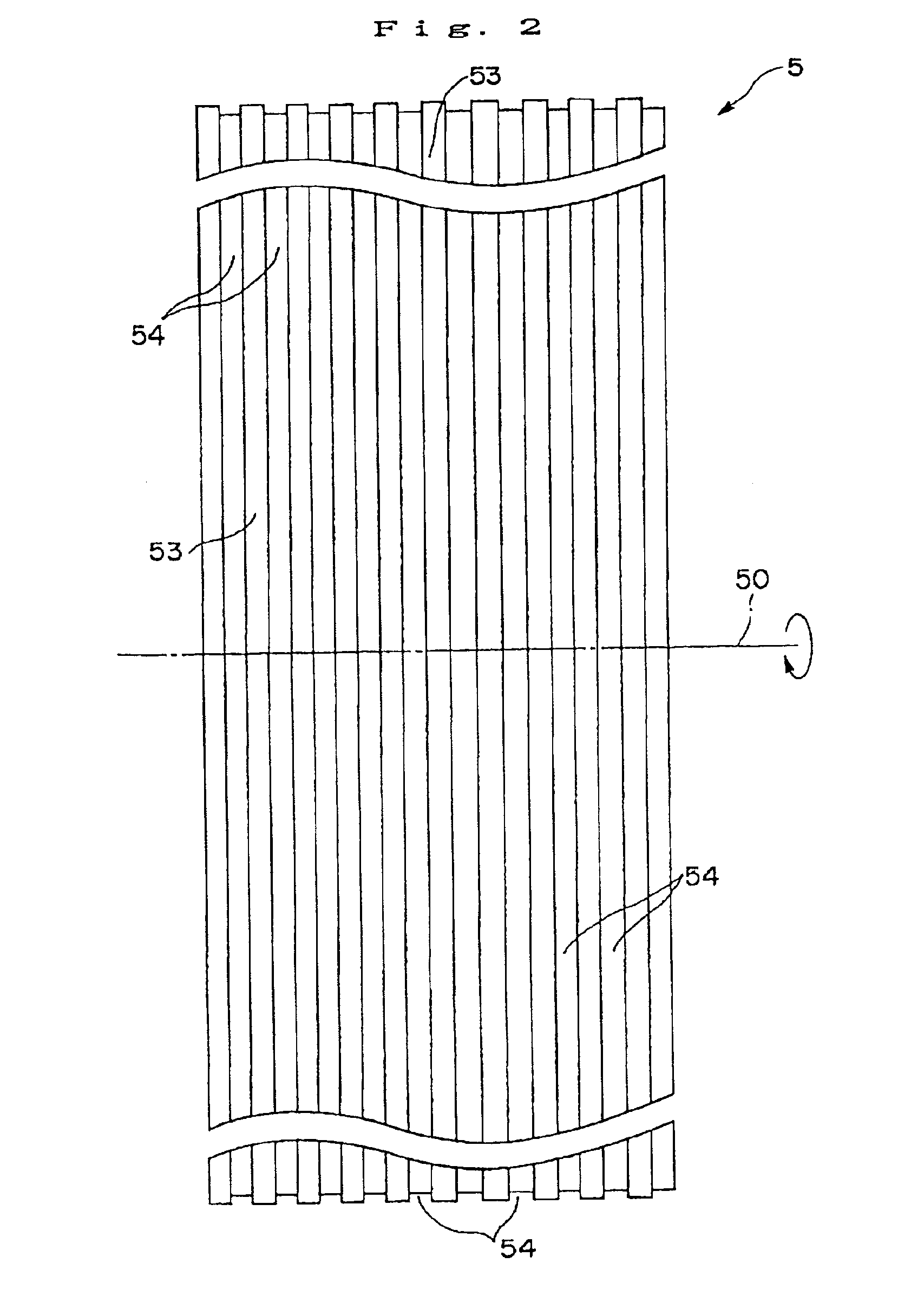
[0180]A cooling roll having the gas expelling means shown in FIGS. 1 to 3 was manufactured, and then a melt spinning apparatus equipped with the cooling roll shown in FIG. 1 was prepared.

[0181]The cooling roll was manufactured as follows.

[0182]First, a roll base (having diameter of 200 mm and width of 30 mm) made of a copper (having heat conductive of 395 W·m−1·K−1 at a temperature of 20° C. Aid coefficient of thermal expansion of 16.5×10⁻⁶K−1 at a temperature of 20° C.) was prepared, and then it was ground so as to have a mirror finishing outer circumferential surface with a surface roughness of Ra 0.07 μm.

[0183]Then, a plurality of grooves 54 which extend in parallel with the rotational direction of the roll base were formed by cutting.

[0184]Next, a surface layer of ZrC (a kind of ceramics) (having heat conductive of 20.6 W·m−1·K−1 at a temperature of 20° C. Aid coefficient of thermal expansion of 7.0×10⁻⁶K−1 at a temperature of 20° C.) was formed onto the outer circumferential su...

examples 2 to 7

[0189]In addition to the above, another six types of cooling rolls each having the same configuration as that of the cooling roll A excepting that the shape and form of the grooves were formed into those shown in FIGS. 9 and 10 were manufactured. Here, it should be noted that these cooling rolls G were manufactured so that the average width of each groove, the average depth of each groove, the average pitch of the adjacent grooves and the angle θ defined between the longitudinal direction of each groove and the rotational direction the cooling roll were different from with each other in each of the cooling rolls. Further, in each of the cooling rolls, three sets of grooves were formed using a lathe having three cutting tools arranged so as to have the same interval so that the adjacent grooves have the same pitch in all the portions in the circumferential surfaces thereof. Then, by replacing the cooling roll of the melt spinning apparatus used in Example 1 with each of these cooling...

example 8

[0190]Further, another cooling roll was also manufactured in the same manner as the cooling roll of Example 2 excepting that the shape and form of the grooves were formed into those shown in FIGS. 11 and 12. Then, in the same manner as Example 1, a melt spun ribbon was manufactured by replacing the cooling roll of the melt spinning apparatus with this cooling roll.


PUM

PropertyMeasurementUnit
widthaaaaaaaaaa
thicknessaaaaaaaaaa
surface roughnessaaaaaaaaaa

Abstract

Disclosed herein is a cooling roll which can provide bonded a magnet having excellent magnetic properties and having excellent reliability. A melt spinning apparatus 1 is provided with a tube 2 having a nozzle 3 at the bottom thereof, a coil 4 for heating the tube and a cooling roll 5 having a circumferential surface 53 in which gas expelling grooves 54 are formed. A melt spun ribbon 8 is formed by injecting the molten alloy 6 from the nozzle 6 so as to be collided with the circumferential surface 53 of the cooling roll 5, so that the molten alloy 6 is cooled and then solidified. In this process, gas is likely to enter between a puddle 7 of the molten alloy 6 and the circumferential surface 53, but such gas is expelled by means of the gas expelling grooves 54.

Description

BACKGROUND OF THE INVENTION[0001]1. Field of the Invention[0002]The present invention relates to a cooling roll, ribbon-shaped magnetic materials, magnetic powders and bonded magnets. More specifically, the present invention relates to a cooling roll, a ribbon-shaped magnetic material formed by using the cooling roll, a magnetic powder formed from the magnetic material and a bonded magnet manufactured using the magnetic powder.[0003]2. Description of the Prior Art[0004]Rare-earth magnetic materials formed from alloys containing rare-earth elements have high magnetic properties. Therefore, when they are used for magnetic materials for motors, for example, the motors can exhibit high performance.[0005]Such magnetic materials are manufactured by the quenching method using a melt spinning apparatus, for example. Hereinbelow, explanation will be made with regard to the manufacturing method using the melt spinning apparatus.[0006]FIG. 20 is a sectional side view which shows the situation ...

Claims


Application Information

Patent Timeline
Patent Type & Authority Patents(United States)
IPC IPC(8): H01F1/12H01F1/057H01F1/032H01F1/153H01F1/055B22D11/06B22F1/00B22F9/04H01F1/053H01F1/06H01F1/08H01F41/02
CPCH01F1/0551H01F1/0558H01F1/0571H01F1/15341H01F1/0578Y10T428/12444Y10T428/12993Y10T428/12389H01F41/02
Inventor ARAI, AKIRAKATO, HIROSHI
Owner SEIKO EPSON CORP
Why Eureka
Try Eureka