Magnetic material manufacturing method, ribbon-shaped magnetic materials, powdered magnetic material and bonded magnets

a magnetic material and manufacturing method technology, applied in the direction of magnets, magnetic bodies, transportation and packaging, etc., can solve the problems of reducing magnetic properties, reducing magnetic properties, and reducing the maximum magnetic energy product (bh)max of magnetic powder, so as to achieve excellent magnetic properties, high maximum magnetic energy product (bhmax), and high magnetic properties

Inactive Publication Date: 2006-11-21
SEIKO EPSON CORP
View PDF25 Cites 2 Cited by
  • Summary
  • Abstract
  • Description
  • Claims
  • Application Information

AI Technical Summary

Benefits of technology

[0163]The content of the magnetic powder in the bonded magnet is not particularly limited, and it is normally determined by considering the kind of the molding method to be used and the compatibility of moldability and high magnetic properties. For example, it is preferred that the content is in the range of 75–99.5 wt %, and more preferably in the range of 85–97.5 wt %.
[0164]In particular, in the case of a bonded magnet manufactured by the compaction molding method, the content of the magnetic powder should preferably lie in the range of 90–99.5 wt %, and more preferably in the range of 93–98.5 wt %.
[0165]Further, in the case of a bonded magnet manufactured by the extrusion molding or the injection molding, the content of the magnetic powder should preferably lie in the range of 75–98 wt %, and more preferably in the range of 85–97 wt %.
[0166]The density ρ of the bonded magnet is determined by factors such as the specific gravity of the magnetic powder contained in the bonded magnet and the content of the magnetic powder, and the void ratio (porosity) of the bonded magnet and the like. In the bonded magnets according to this invention, the density ρ is not particularly limited to a specific value, but it is preferable to be in the range of 4.5–6.6 Mg / m3, and more preferably in the range of 5.5–6.4 Mg / m3.
[0167]In this invention, since the remanent magnetic flux density and the coercive force of the magnetic powder are high, the bonded magnet formed from the magnetic powder provides excellent magnetic properties (especially, high maximum magnetic energy product (BH)max) even when the content of the magnetic powder is relatively low. In this regard, it goes without saying that it is possible to obtain the excellent magnetic properties in the case where the content of the magnetic powder is high.
[0168]The shape, dimensions and the like of the bonded magnet manufactured according to this invention are not particularly limited. For example, as to the shape, all shapes such as columnar shape, prism-like shape, cylindrical shape (annular shape), circular shape, plate-like shape, curved plate-like shape, and the like are acceptable. As to the dimensions, all sizes starting from large-sized one to ultraminuaturized one are acceptable. However, as repeatedly described in this specification, the present invention is particularly advantageous when it is used for miniaturized magnets and ultraminiaturized magnets.

Problems solved by technology

The rare-earth elements are liable to oxidize.
As a result, at portions of the melt spun ribbon where such dimples are formed, the crystal grain size of the alloy becomes coarse, which results in lowered magnetic properties.
Therefore, bonded magnets, formed from such magnetic powder can have only poor magnetic properties, and corrosion resistance thereof is also low.

Method used


Image

  • Magnetic material manufacturing method, ribbon-shaped magnetic materials, powdered magnetic material and bonded magnets
  • Magnetic material manufacturing method, ribbon-shaped magnetic materials, powdered magnetic material and bonded magnets
  • Magnetic material manufacturing method, ribbon-shaped magnetic materials, powdered magnetic material and bonded magnets

Examples


example 1

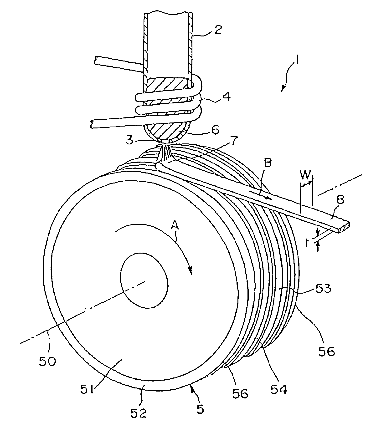
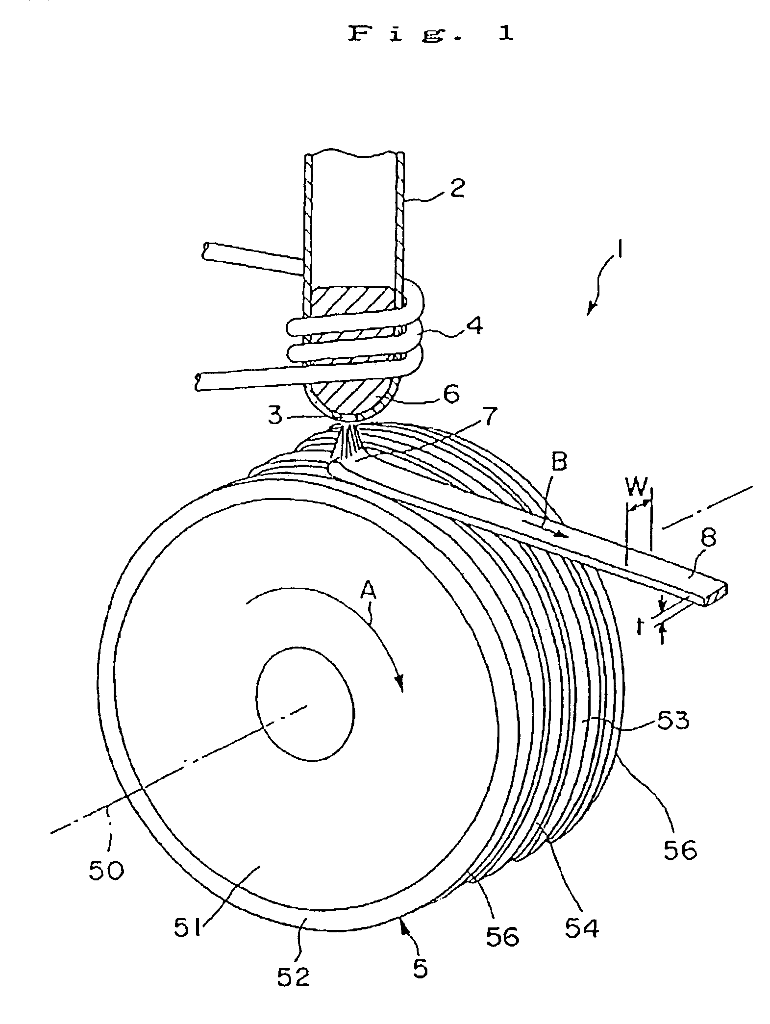
[0201]A cooling roll A having the dimple correcting means shown in FIGS. 1 to 3 was manufactured, and then a melt spinning apparatus equipped with the cooling roll A shown in FIG. 1 was prepared.

[0202]The cooling roll A was manufactured as follows.

[0203]First, a roll base (having diameter of 200 mm and width of 30 mm) made of a copper (having heat conductive of 395 W·m−1·K−1 at t a temperature of 20° C. and coefficient of thermal expansion of 16.5×10⁻⁶K−1 at a temperature of 20° C.) was prepared, and then it was ground so as to have a mirror finishing outer circumferential surface with a surface roughness of Ra 0.07 μm.

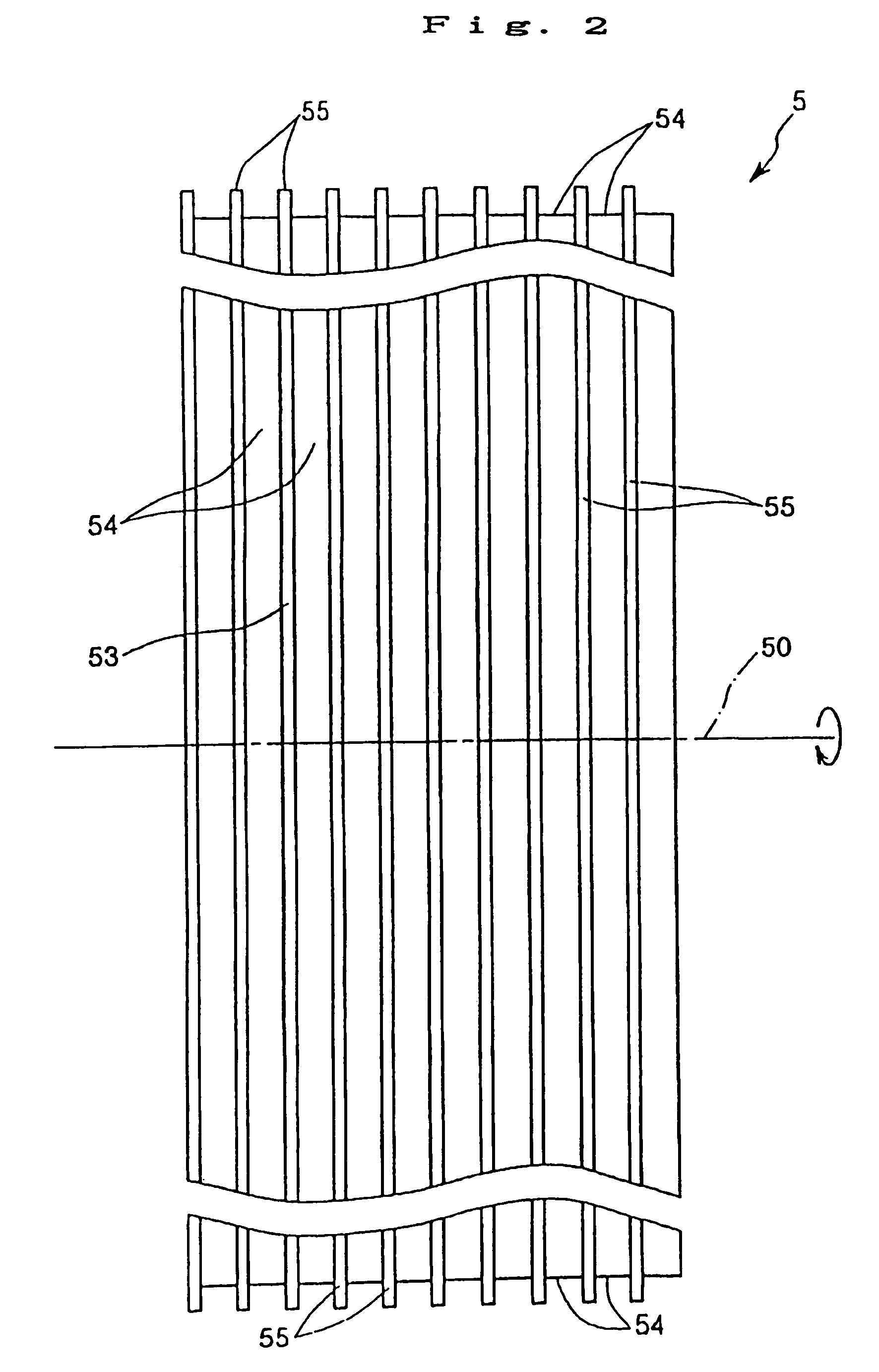
[0204]Then, a plurality of grooves 54 which extend in parallel with the rotational direction of the roll base were formed by cutting.

[0205]As a result of the formation of the grooves, the portions remaining between the adjacent grooves 54 were used as ridges.

[0206]Next, a surface layer of ZrC (a kind of ceramics) (having heat conductivity of 20.6 W·m−1·K−1 at t a temp...

example 2

[0235]Ten types of melt spun ribbons (sample Nos. 2a, 2b, 2c, 2d, 2e, 2f, 2g, 2h, 2i and 2j) were manufactured using the cooling rolls A to J in the same manner as Example 1 described above excepting that the alloy composition of each melt spun ribbon was Nd11.5Febal.B4.6.

[0236]Then, for each of the ten melt spun ribbons (samples Nos. 2a to 2j) which were respectively manufactured using each of the cooling rolls (A to J), the surface condition thereof was observed by a scanning electronic micrometer (SEM). As a result, it was confirmed that in each of the melt spun ribbons of the samples Nos. 2a to 2i (present invention), the surface shape or form (groove or ridges) of the cooling roll was transferred to the roll contact surface of the melt spun ribbon so that corresponding ridges or grooves are formed therein and dimples are produced with a state that they are divided by thus formed ridges or grooves (in particular, the grooves). In contrast, in the melt spun ribbon of the sample N...

example 3

[0250]Ten types of melt spun ribbons (sample Nos. 3a, 3b, 3c, 3d, 3e, 3f, 3g, 3h, 3i and 3j) were manufactured using the cooling rolls A to J in the same manner as Example 1 described above excepting that the alloy composition of each melt spun ribbon was Nd14.2(Fe0.85Co0.15)bal.B6.8.

[0251]Then, for each of the ten melt spun ribbons (samples Nos. 3a to 3j) which were respectively manufactured using each of the cooling rolls (A to J), the surface condition thereof was observed by a scanning electronic micro meter (SEM). As a result, it was confirmed that in each of the melt spun ribbons of the samples Nos. 3a to 3i (present invention), the surface shape or form (groove or ridges) of the cooling roll was transferred to the roll contact surface of the melt spun ribbon so that corresponding ridges or grooves are formed therein and dimples are produced with a state that they are divided by thus formed ridges or grooves (in particular, the grooves). In contrast, in the melt spun ribbon of...


PUM

PropertyMeasurementUnit
depthaaaaaaaaaa
heightaaaaaaaaaa
areaaaaaaaaaaa

Abstract

A magnetic material manufacturing method, a ribbon-shaped magnetic material manufactured by the method, a powdered magnetic material formed from the ribbon-shaped magnetic material and a bonded magnet manufactured using the powdered magnet material are disclosed. The method and the magnetic materials can provide magnets having excellent magnetic properties and reliability. A melt spinning apparatus 1 is provided with a tube 2 having a nozzle 3 at the bottom thereof, a coil 4 for heating the tube and a cooling roll 5 having a circumferential surface 53 on which dimple correcting means is provided. A melt spun ribbon 8 is formed by injecting the molten alloy 6 from the nozzle 3 so as to be collided with the circumferential surface 53 of the cooling roll 5 in an inert gas atmosphere (ambient gas) such as helium gas, so that the molten alloy 6 is cooled and then solidified. In this process, dimples to be produced on a roll contact surface of the melt spun ribbon are divided by the dimple correcting means, thereby preventing formation of huge dimples.

Description

CROSS-REFERENCE TO RELATED APPLICATIONS[0001]This application is a divisional of U.S. patent application Ser. No. 09 / 871,592 filed on May 30, 2001, which is now U.S. Pat. No. 6,830,633. This application claims the benefit of Japanese Patent Applications 2000-159772, filed May 30, 2000, and 2000-399881, filed Dec. 28, 2000. The disclosures of the above applications are incorporated herein by reference in their entirety.BACKGROUND OF THE INVENTION[0002]1. Field of the Invention[0003]The present invention relates to a magnetic material manufacturing method ribbon-shaped magnetic materials, powdered magnetic materials and bonded magnets. More specifically the present invention relates to a magnetic material manufacturing method, a ribbon-shaped magnetic material manufactured by the method, a powdered magnetic material formed from the ribbon-shaped magnetic material and a bonded magnet manufactured using the powdered magnetic material.[0004]2. Description of the Prior Art[0005]Rare-earth...

Claims


Application Information

Patent Timeline
Patent Type & Authority Patents(United States)
IPC IPC(8): H01F1/26B22D11/06B22F1/00B22F9/08C22C1/04C22C38/00H01F1/053H01F1/057H01F1/08H01F41/02
CPCB22D11/0611B22D11/0651B22F1/0044B22F9/08B82Y25/00C22C1/0441H01F1/0571H01F1/0578B22F9/10B22F9/04B22F2009/048B22F2009/0888B22F2998/00B22F2998/10B22F2201/10B22F1/07H01F41/02
Inventor ARAI, AKIRAKATO, HIROSHI
Owner SEIKO EPSON CORP
Why Eureka
Try Eureka