[0020] The accumulated losses in soft iron components of the
magnetic circuit in known vibrator designs are manifested in the fact that the
electrical impedance become more resistive than would be the case without losses. This means that the designs of today has a
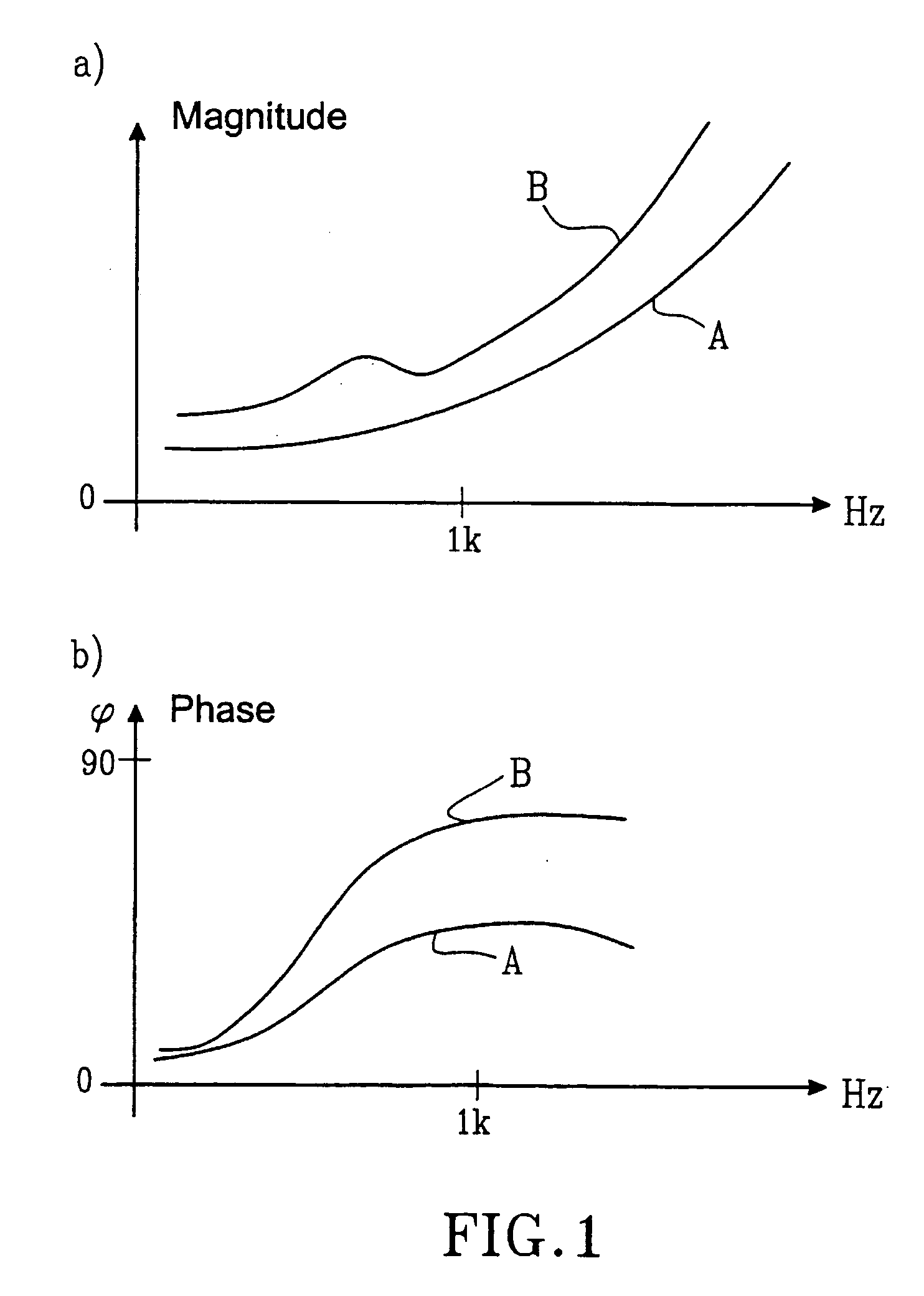
phase angle of the
electrical impedance that hardly exceeds 60 degrees, which is to be compared with the
phase angle that can be obtained in the present invention, having a laminated bobbin body, which is about 80 to 85 degrees, cf FIG. 1B. In this new invention a more inductive characteristic of the
electrical impedance is obtained which means on one hand that the
eddy current losses have been reduced, on the other hand that the electrical impedance has got a higher
inductance. This more purified inductive characteristic, being a concrete effect of the invention, can be utilized in such a way that the vibrator can be tailor-made to become extremely efficient in certain frequency bands, or having extremely
high impedance at other frequency bands. This optimization may easily be carried out using external electrical components.
[0021] The technique using laminated cores has been tested in quite other applications, such as in transformers, electrical engines, and loud speakers for air conductance, but never for vibrators for
bone conduction applications. An application where lamination of parts of the magnetic flux path has been proposed is known from U.S. Pat. No. 3,632,904. It is proposed that lamination should be used in a conventional loud speaker of “moving coil type” or “
voice coil type”. This loud speaker functions according to a quite different principle than vibrators of variable reluctance type. A piquant detail in connection herewith is that, as the laminations are carried out in accordance with the description and the figures of U.S. Pat. No. 3,632,904, no reduction of the
eddy current losses will occur. The laminations are actually placed 90 degrees perpendicular to the
signal flux, which will not reduce
eddy current losses as these are induced in the same plane. In known circular symmetrical
loudspeaker constructions having
voice coil the lamination is difficult to carry out as these in such cases should mean cylinders having a successively changing
diameter should be fitted into each other provided with isolating
layers in between. In U.S. Pat. No. 3,935,398 laminations are shown in a small air loud speaker for
air conduction hearing aids. Here lamination has been used for a part of the magnetic flux path, however, not to the most important part thereof, viz. the iron core circumvented by the coil. In this type of loud speakers where the bobbin core consists of in thin band form, which is the movable part of the loud speaker transferring vibrations to the air membrane lamination of the bobbin body / iron core can not be used. There are several reasons for that laminations are not used in the bone conduction vibrators of today. One reason is for not having tested lamination is that an exact analysis of the electro magnetic function of the bone conduction vibrators of today is practically impossible to carry out and consequently, nobody has explicitly pointed at the magnitude of the problem. It is first after considerable tests as the full potential of the present invention can be understood. Another reason for not having tested laminations may have been the fact that the problem of eddy currents have not been that large, as it is in the new constructions according to SE 0000810-2 and nobody has apparently thus tried to solve the problem in the way as proposed in the present invention. A third reason is also that laminations has been difficult to carry out from a manufacturing point of view and to a reasonable cost because conventional vibrators of today have
circular symmetry.
[0022] The application of the present invention is not restricted to
bone tissue transmitting hearing aids and audio meter vibrators but may also be used in other loud speaker applications and as
vibration exciter or as a bone conduction
microphone.DESCRIPTION OF THE FIGURES
[0023]FIG. 1. The magnitude of the impedance (a) and phase (b) characteristics of a variable reluctance vibrator of known type (A) and according to the present invention (B);


