
Method, device, and tool for chamfering the front-end edges of the inter-teeth grooves of a gear

a gear and interteeth technology, applied in the direction of gear teeth, milling equipment, applications, etc., can solve the problem of saving significant time for manufactur

Active Publication Date: 2006-09-12
FETTE
View PDF16 Cites 35 Cited by
  • Summary
  • Abstract
  • Description
  • Claims
  • Application Information

AI Technical Summary

Benefits of technology

"The invention provides a method and device for removing burrs from toothed gears using a deburring tool that is integrated with a hobbing cutter or separately fixed on the machine tool. The deburring tool has cutting teeth and clamping grooves that interact with the inter-teeth grooves of the gear. The method allows for chamfering in two or more steps and reduces the need for machining equipment and retooling times. The device includes a fixed deburring tool with cutting teeth and clamping grooves, and chamfering can also be performed on the front-end edges of the tooth heads. The deburring tool can be resharpened on the machine tool. The invention also provides a toothed gear with helically extending teeth that have identical points on the same fly circle, which is different from a side milling cutter used as a tooth-forming tool."

Problems solved by technology

This saves significant time for manufacture.

Method used


Image

  • Method, device, and tool for chamfering the front-end edges of the inter-teeth grooves of a gear
  • Method, device, and tool for chamfering the front-end edges of the inter-teeth grooves of a gear
  • Method, device, and tool for chamfering the front-end edges of the inter-teeth grooves of a gear

Examples


Embodiment Construction

[0025]While this invention may be embodied in many different forms, there are described in detail herein a specific preferred embodiment of the invention. This description is an exemplification of the principles of the invention and is not intended to limit the invention to the particular embodiment illustrated

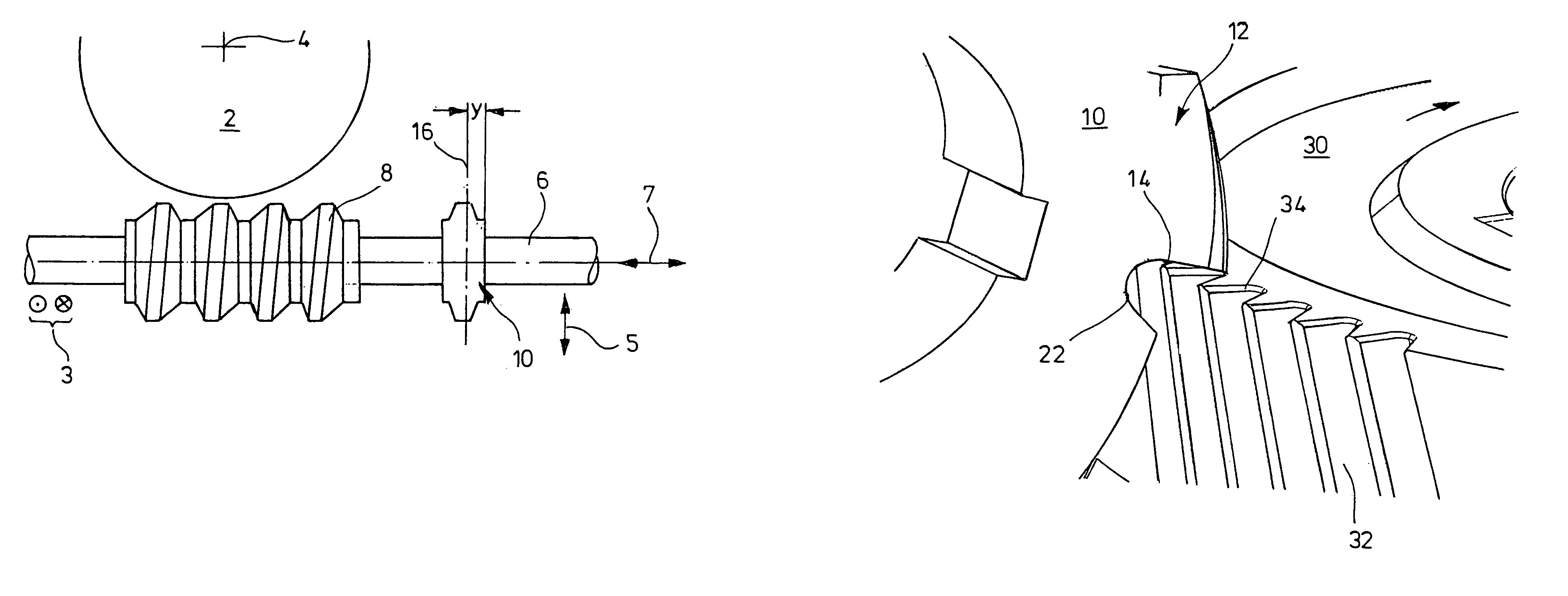
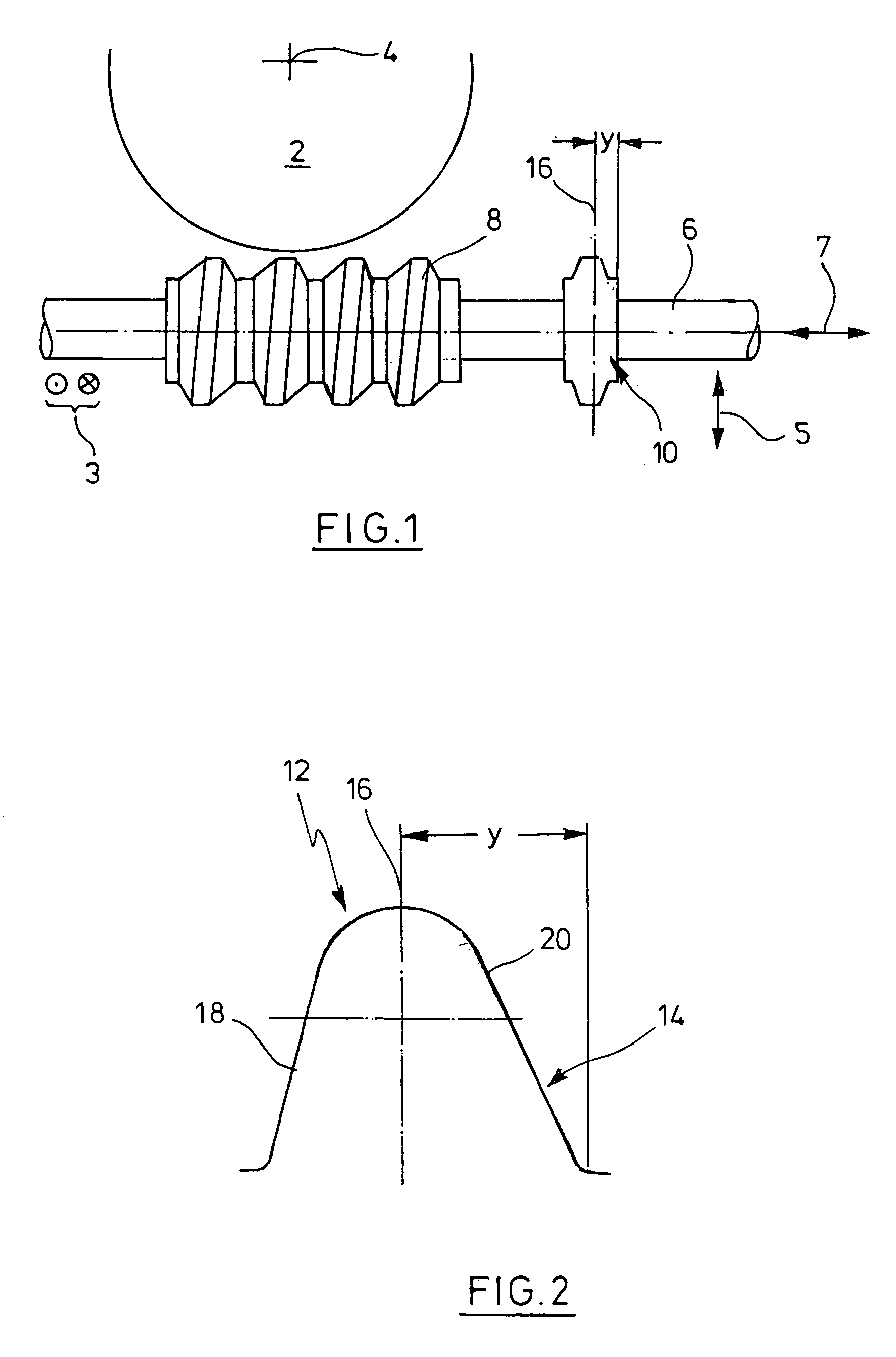
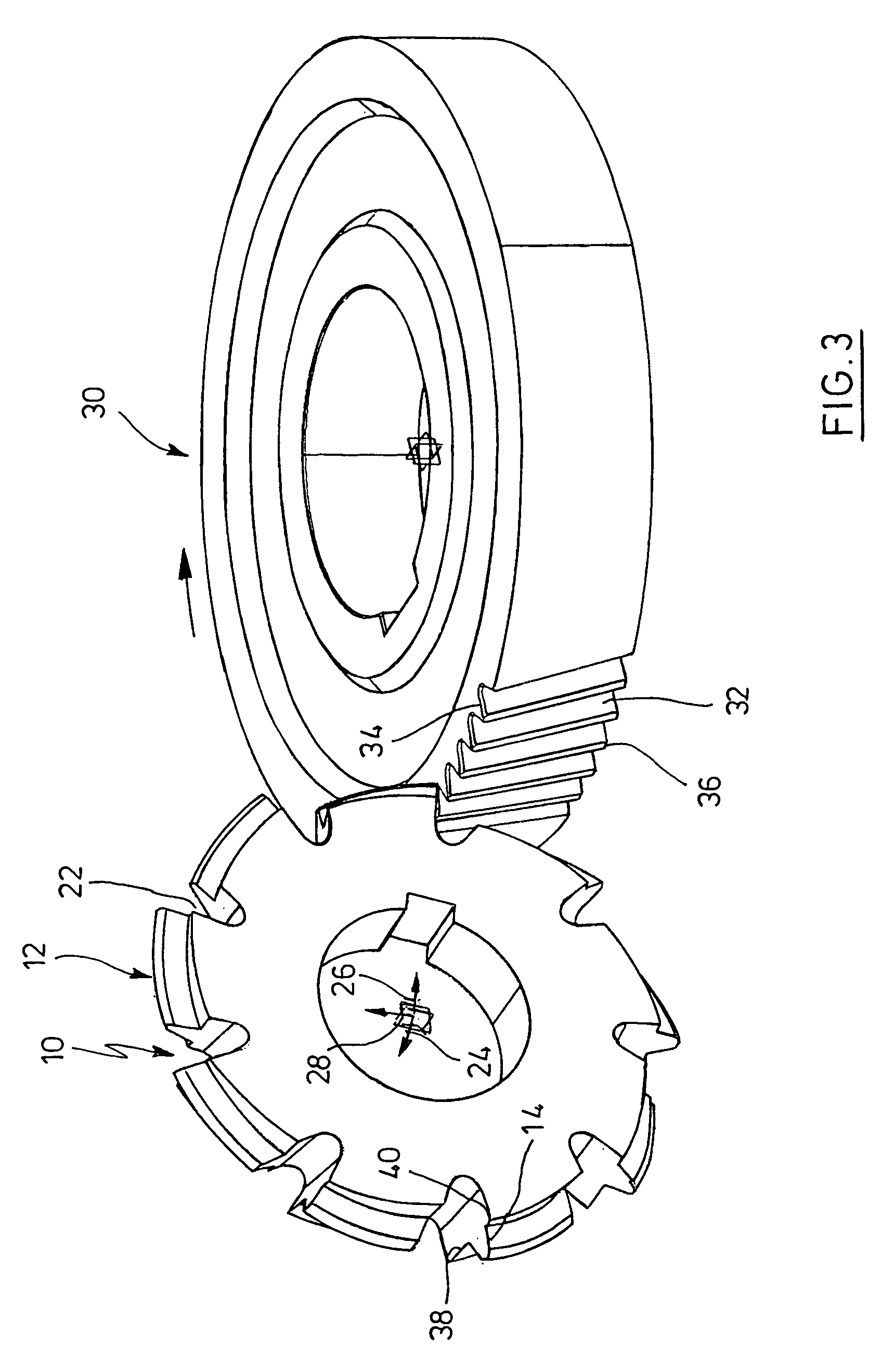
[0026]In FIG. 1, a gear blank is outlined at 2 which is loaded on a machine tool in a manner which is not shown in detail and is rotationally driven about an axis 4. The axis is perpendicular to the plane of the drawing, for example. A shaft 6 of the machine tool has mounted thereon a hobbing cutter 8. The shaft 6 can be shifted in space as is outlined by the two-ended arrow 7, the two-ended arrow 5, and the directions shown at 3. Rotating the tool shaft 6 and providing the correct setting and the correct feed motion and advancement produces a spur gear. This process is generally known and is not thought to be discussed in detail.

[0027]The shaft 6 has mounted thereon a deburri...


PUM

PropertyMeasurementUnit
circumferenceaaaaaaaaaa
speedaaaaaaaaaa
chamfering angleaaaaaaaaaa

Abstract

A method for the manufacture of a toothed gear from a gear blank wherein the gear blank loaded into a machine tool and rotationally driven is machined by a hobbing cutter disposed on a rotationally driven tool shaft and the rough-hobbed gear, once produced, is subsequently cleared of burr by means of a rotationally driven deburring tool by causing it to chamfer the front-end edges of the inter-teeth grooves, wherein the number of revolutions of said deburring tool and rough-machined gear has a constant ratio, wherein the removal of burr is performed on said rough-machined gear invariably loaded on said machine tool in a continuous pass by using a deburring tool which is similar to a side milling cutter, has cutting teeth, and is fixedly disposed for rotation on the shaft of said hobbing cutter, wherein the front-end edges of the inter-teeth grooves are successively machined in the way of a gear hobbing process, and wherein said shaft is changed from the gear hobbing setting over to a burr removal setting.

Description

CROSS-REFERENCE TO RELATED APPLICATIONS[0001]Not applicable.STATEMENT REGARDING FEDERALLY SPONSORED RESEARCH[0002]Not applicable.BACKGROUND OF THE INVENTION[0003]The invention relates to a method for the manufacture of a toothed gear device for the manufacture of a toothed gear and a tool for deburring the front-end edges of the inter-teeth grooves of a gear.[0004]It is known to produce toothed gears by means of so-called hobbing cutters. Hobbing cutters have a worm as a geometrical body to start from. When the worm is given clamping grooves hobbed teeth are obtained which, when subjected to relieving, become then able to cut. After gear-like workpieces are hobbed the front-end edges of the inter-teeth grooves and tooth heads will have sharp edges, specifically at the side at which the hobbing tool exits. It is known to remove the burr in a manual operation. Further, it is known to remove the burr by grinding, profile milling or by means of press rolling.[0005]DE 199 02 035 has made...

Claims


Application Information

Patent Timeline
Patent Type & Authority Patents(United States)
IPC IPC(8): B23P23/00B23F19/10B23F21/16B23F21/12
CPCB23F19/10B23F21/12Y10T29/5176Y10T29/5147Y10T409/101749Y10T409/10159Y10T409/108586Y10T409/10477Y10T29/49476Y10T409/106201Y10T409/10795Y10T409/101113B23F21/005
Inventor WOLFF, ALFREDTHIESIES, SIEGFRIEDCARMINCKE, WOLFGANG
Owner FETTE
Learn More