

Vacuum casting die
- Summary
- Abstract
- Description
- Claims
- Application Information
AI Technical Summary
Benefits of technology
Problems solved by technology
Method used
Image

Examples
Embodiment Construction
[0020]Preferred embodiments of the present invention will be described in detail below while referring to the attached drawings.
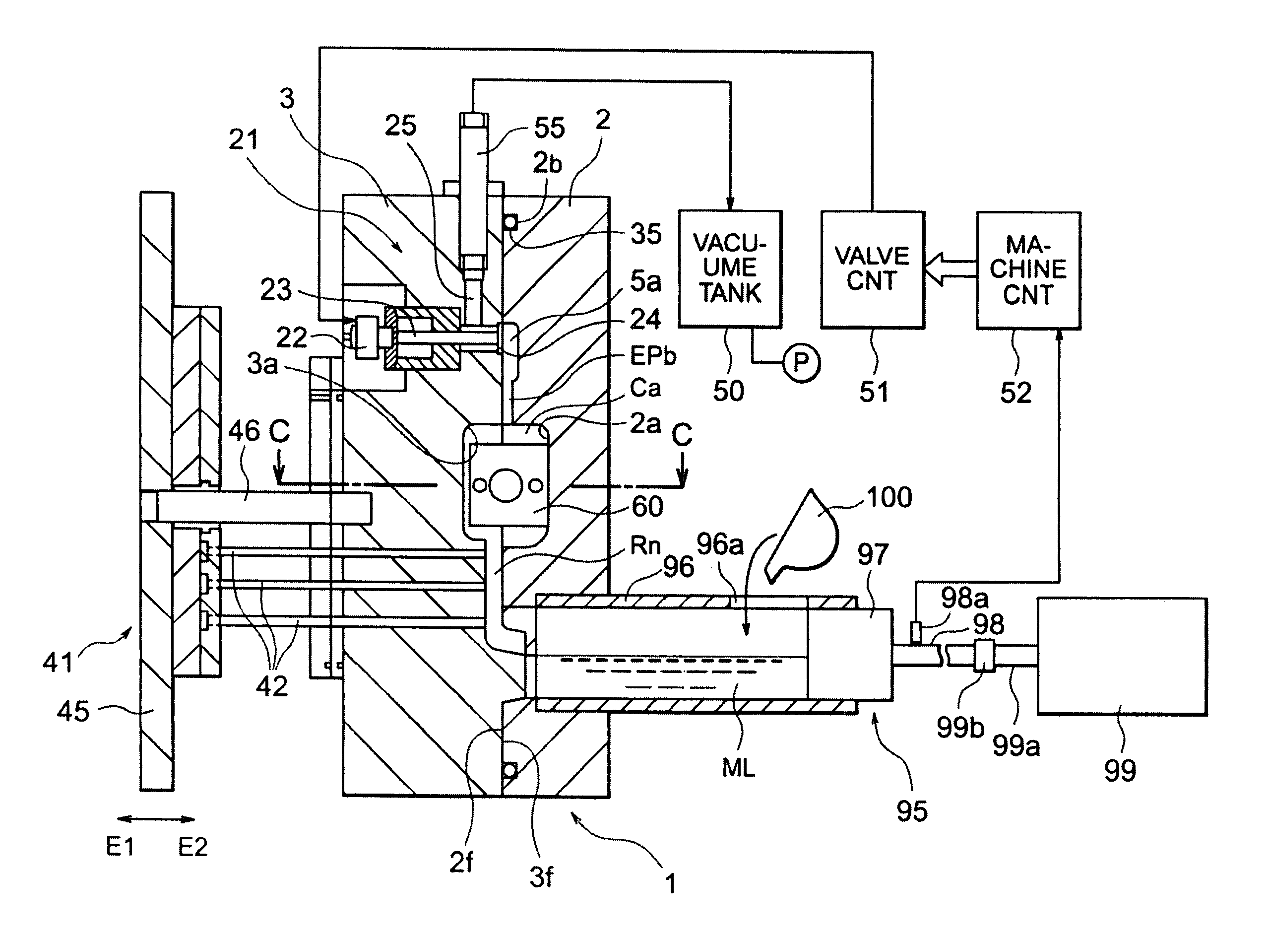
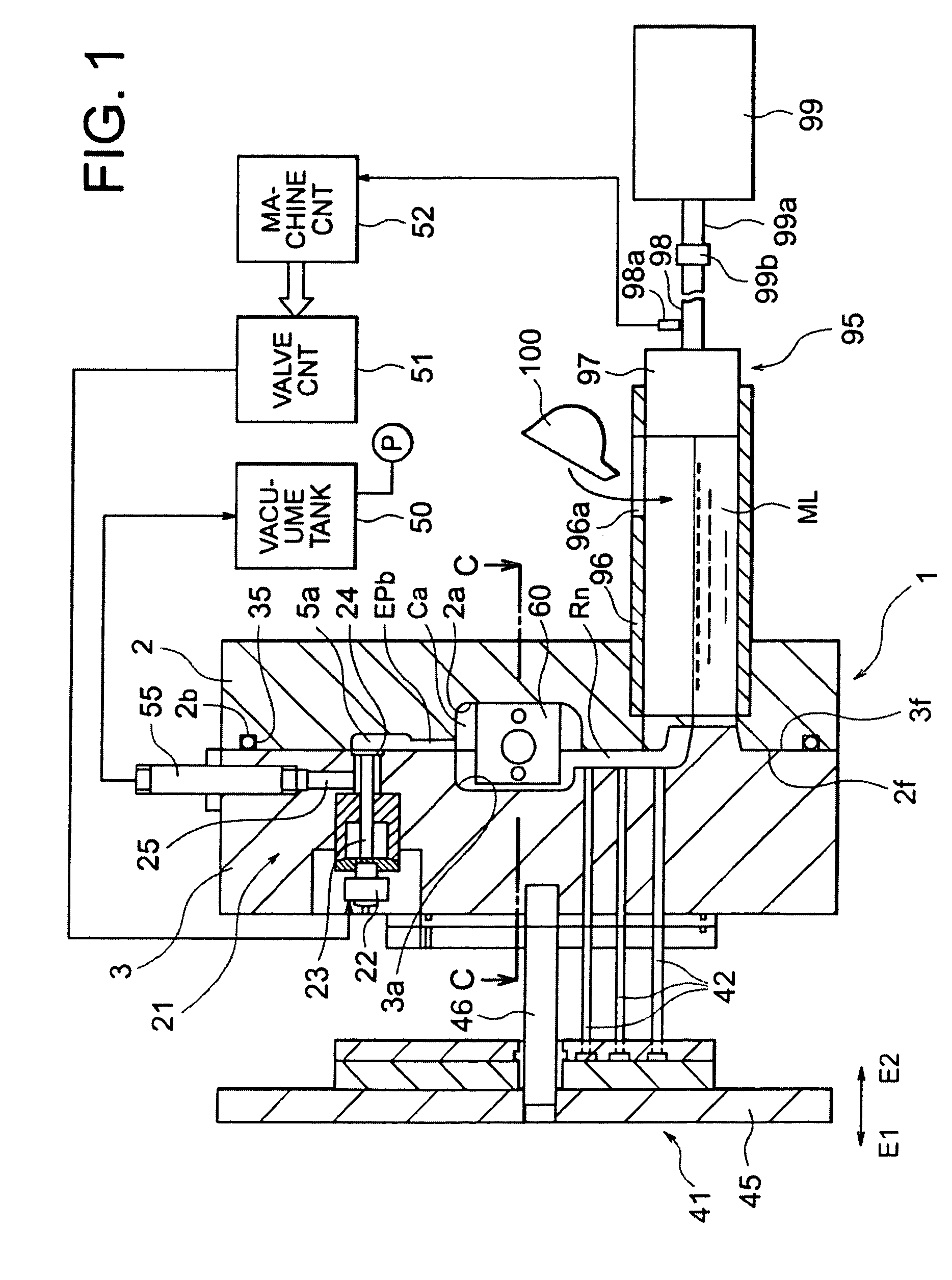
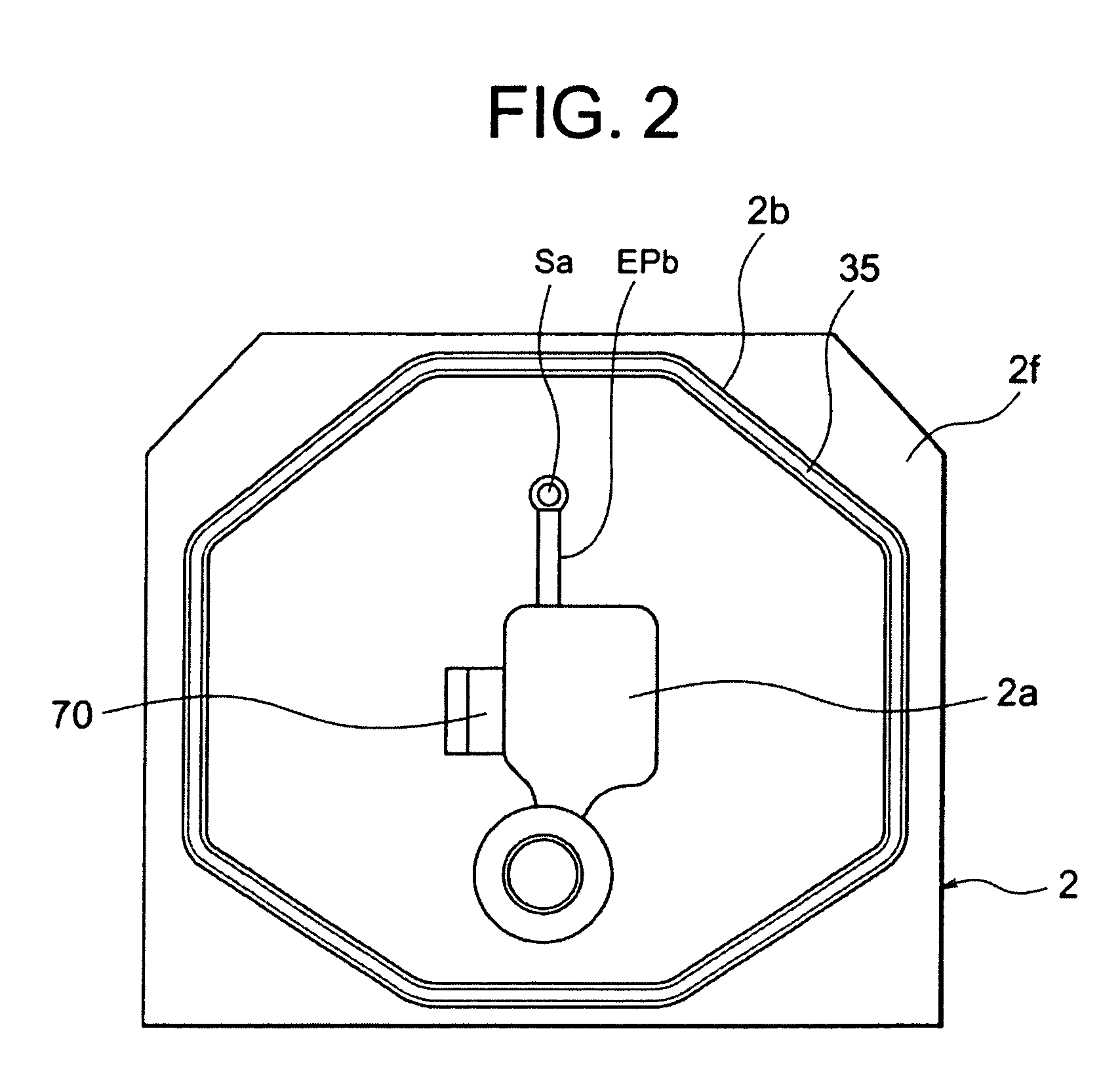
[0021]FIG. 1 is a cross-sectional view of the structure of a vacuum casting die according to an embodiment of the present invention. FIG. 2 is a view of the structure of the mating face of a fixed die, FIG. 3 is a view of the structure of the mating face of a movable die, and FIG. 4 is an enlarged cross-sectional view along the direction of the C—C line of FIG. 1 of the area around the slide core.
[0022]As shown in FIG. 1, the vacuum casting die 1 according to the present embodiment has a fixed die 2 and a movable die 3 corresponding to the pair of dies of the claims of the present invention.
[0023]The fixed die 2 is fixed to a fixed die plate of a not shown mold clamping apparatus. The movable die 3 is fixed to a not illustrated movable die plate provided movably with respect to the fixed die plate. When the mating face 3f of the movable die 3 contacts the m...
PUM
 Abstract
Description
Claims
Application Information