

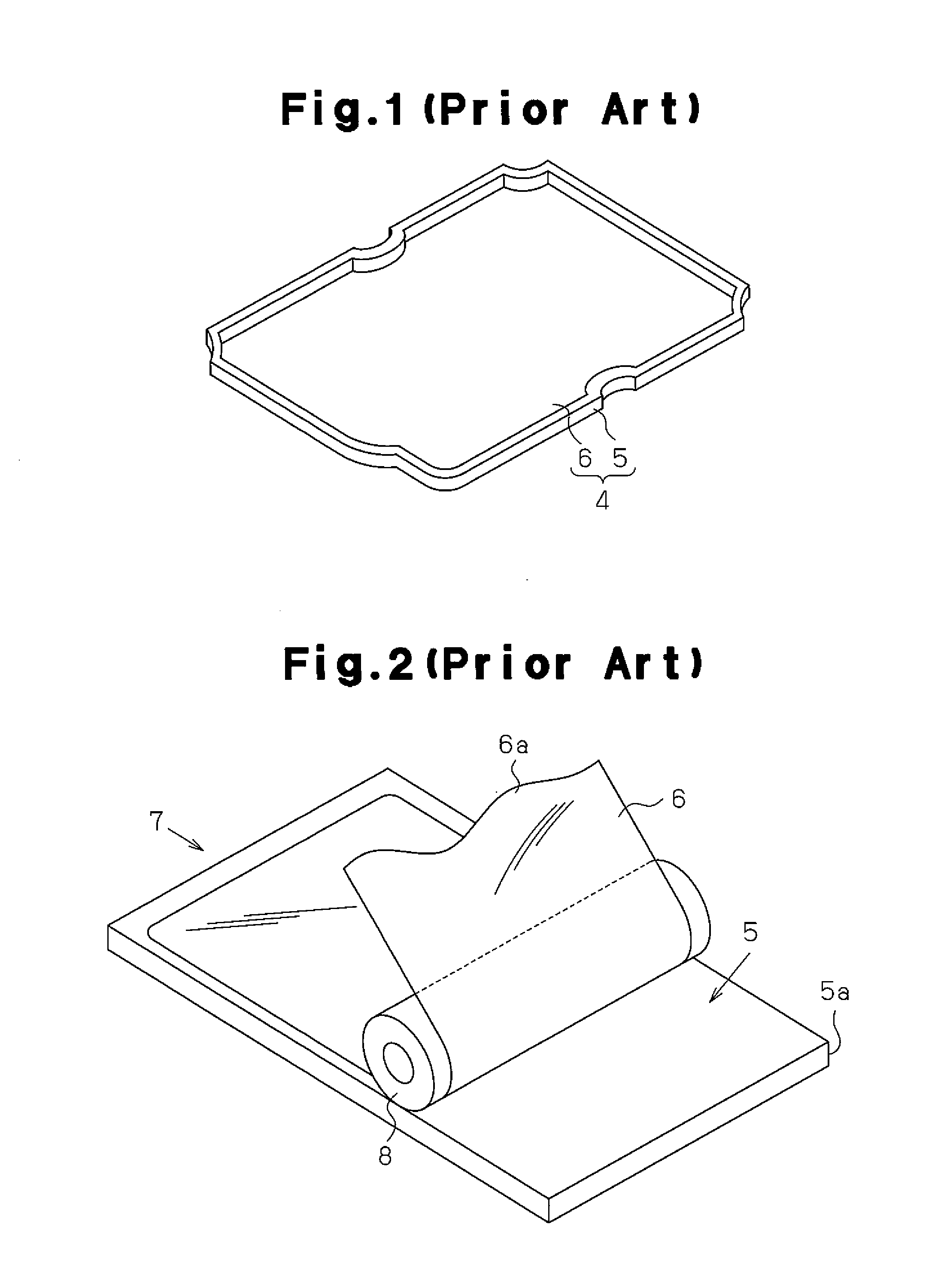
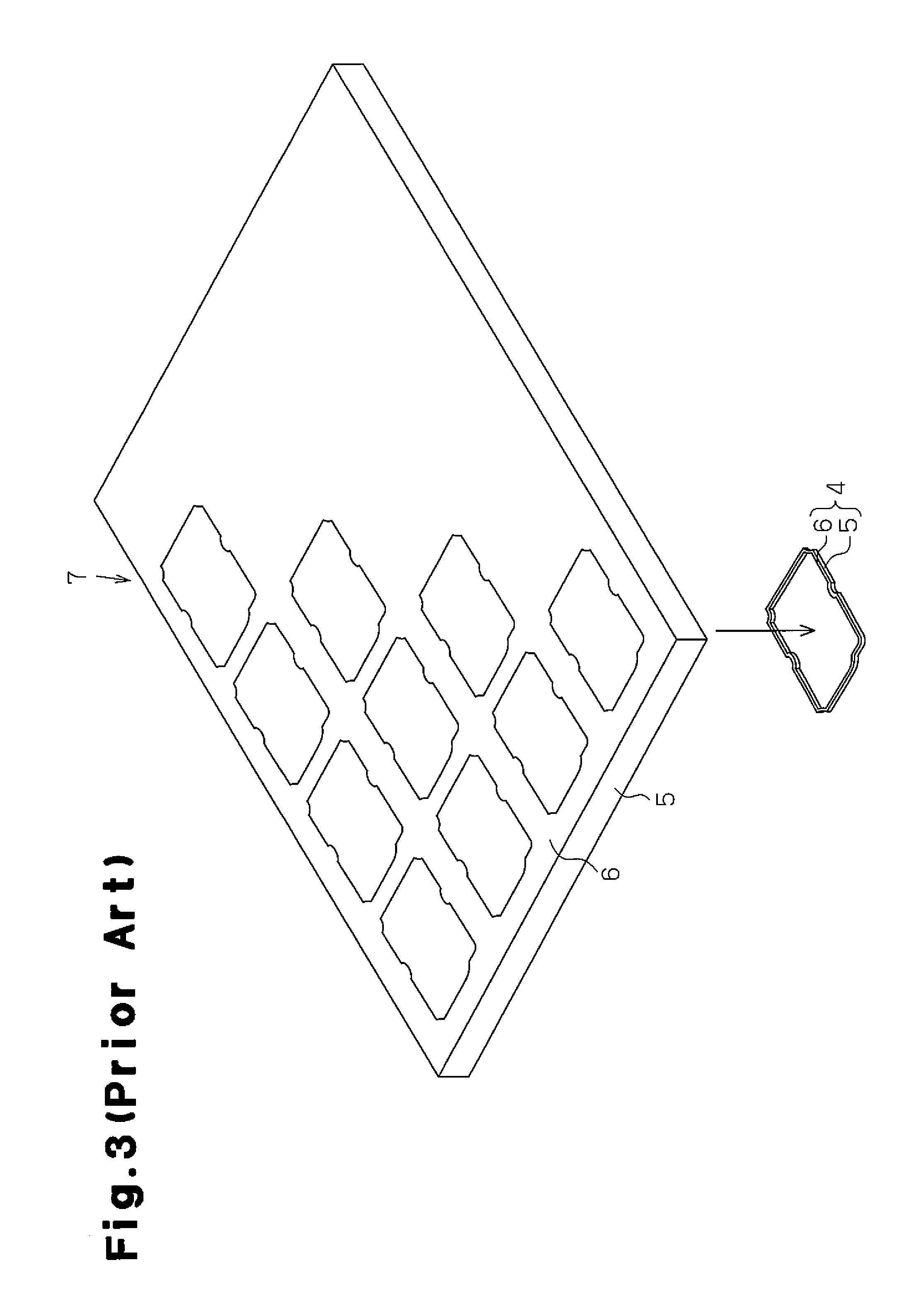
Seal structure using gasket
- Summary
- Abstract
- Description
- Claims
- Application Information
AI Technical Summary
Benefits of technology
Problems solved by technology
Method used
Image

Examples
first embodiment
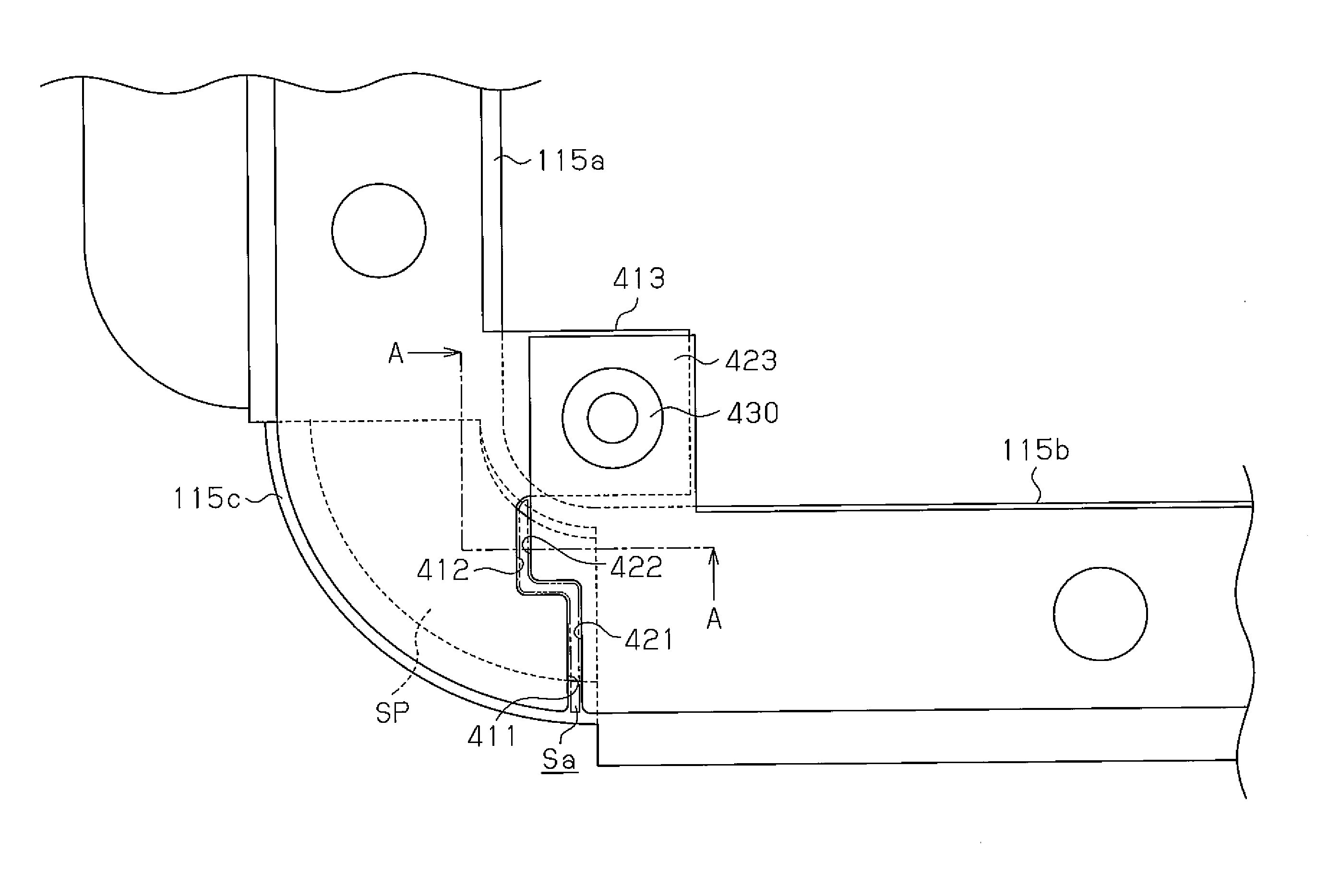
[0046]A seal structure using a gasket according to a first embodiment of the present invention will now be described with reference to FIGS. 6 to 12.
[0047]FIG. 6 shows a battery pack 100 to which a seal structure according to a first embodiment of the present invention is applied. The battery pack 100 is arranged on a vehicle frame Fr, which forms part of a bed in a truck that serves as an electric vehicle or a hybrid vehicle. The battery pack 100 is used as a power unit, which is a power source for supplying power to an electric motor that functions as a main power source or auxiliary power source of the truck.
[0048]FIG. 7 is an exploded view of the battery pack 100. The battery pack 100 includes a battery container that accommodates a battery stack 200, which includes a plurality of battery modules 210 (rechargeable batteries). The battery container is a closed box and formed by a lower case 110 and an upper case 120, each having a rectangular opening. In the first embodiment, the...
second embodiment
[0071]A seal structure according to a second embodiment of the present invention will now be described with reference to FIGS. 13 and 14 centering on differences from the first embodiment. The seal structure of the present embodiment is basically the same as the first embodiment. Like or same reference numerals are given to those components that are the same as the corresponding components of the first embodiment. Such components will not be described.
[0072]Referring to FIG. 13, in the same manner as the first embodiment, a gasket 500 of the second embodiment has a closed tetragonal shape that conforms to the shape of the lower flange 115 and upper flange 124 and includes four corners. The gasket 500 includes first to fourth segments 510, 520, 530, and 540, each corresponding to one side of the gasket 400.
[0073]The segments 510 to 540 each include ends defining separated end portions 501. Each separated end portion 501 includes an inclined face that extends along a diagonal line of ...
third embodiment
[0082]A seal structure according to a third embodiment of the present invention will now be described with reference to FIGS. 15 and 16 centering on differences from the first and second embodiments. The seal structure of the present embodiment is basically the same as the first and second embodiments. Like or same reference numerals are given to those components that are the same as the corresponding components of the first and second embodiments. Such components will not be described.
[0083]As shown in FIG. 15, in the third embodiment, the second and fourth segments 520 and 540 respectively include positioning flaps 521 and 541. The second and fourth segments 520 and 540 respectively correspond to long sides 115d and 115e of the lower flange 115, which are relatively long.
[0084]The long side 115e of the lower flange 115 includes an expanded portion 115f, which expands at a location corresponding to the air outlets 113, and a straight portion 115g, which extends straight from the ex...
PUM
 Abstract
Description
Claims
Application Information