Starter motor having seal plate to seal bearing box formed in end frame

Active Publication Date: 2009-05-28
DENSO CORP
View PDF16 Cites 5 Cited by
  • Summary
  • Abstract
  • Description
  • Claims
  • Application Information

AI Technical Summary

Benefits of technology

[0014]With the above configuration, the open end of the bearing box formed in the end frame is hermetically sealed only by attaching the seal plate on the end face of the end frame. Therefore, compared to the bearing cover disclosed by Japanese Patent No. 3575359, it is possible to much more easily seal the inside of the bearing box from the outside.
[0015]Further, since the seal plate is flexible, it can be reliably prevented from being detached from the end face of the end frame due to heat generated in the starter motor and/or the influence of high temperature inside the engine compartment in

Problems solved by technology

In the above starter motor, since the bearing cover 140 is made of rubber or soft resin, it is difficult to control the dimension of the bearing cover 140.
Moreov

Method used


Image

  • Starter motor having seal plate to seal bearing box formed in end frame
  • Starter motor having seal plate to seal bearing box formed in end frame
  • Starter motor having seal plate to seal bearing box formed in end frame

Examples


Example

First Embodiment

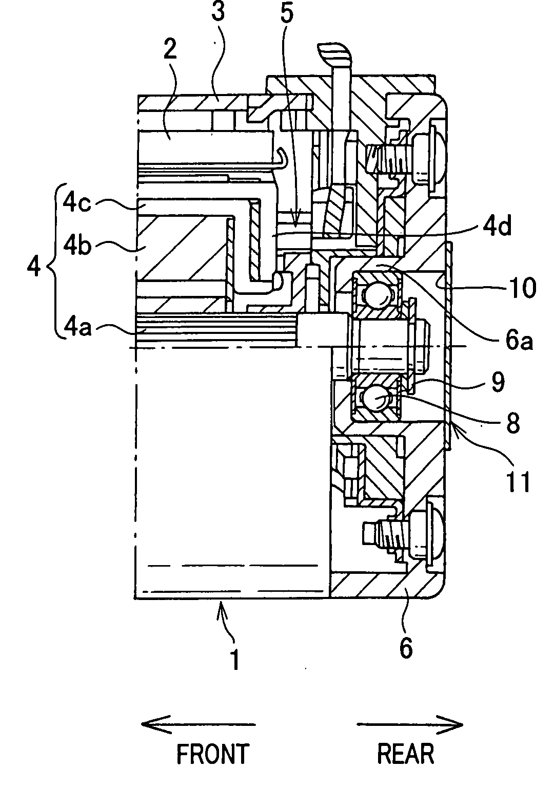
[0037]FIG. 1A shows the overall structure of a starter motor 1 according to the first embodiment of the invention. The starter motor 1 is designed to be used in an engine starter to generate torque for starting an engine of a motor vehicle.

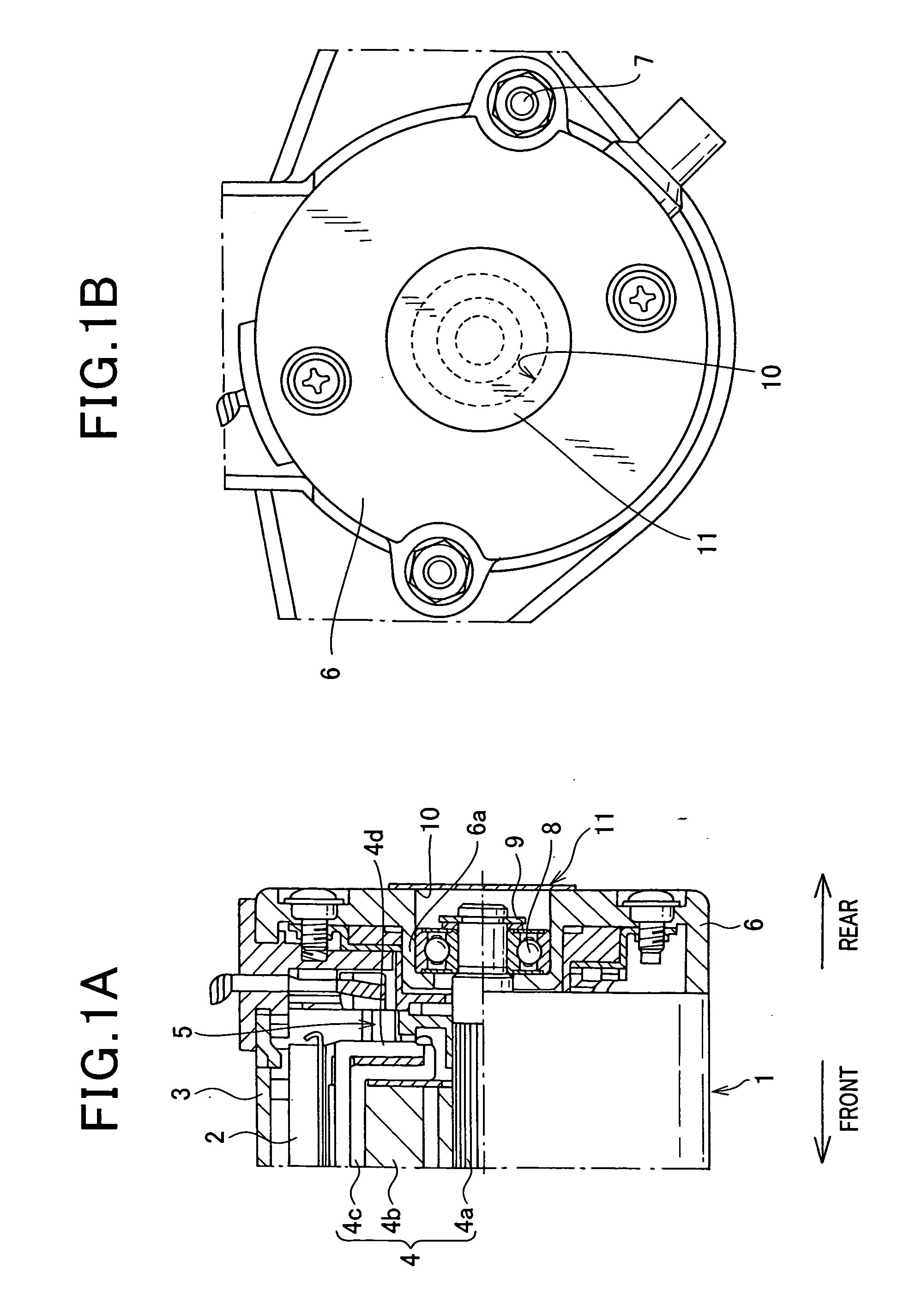
[0038]As shown in FIG. 1A, the starter motor 1 includes a magnetic field system 2 for creating a magnetic field, a cylindrical yoke 3 that surrounds the magnetic field system 2, an armature 4 that is surrounded by the magnetic field system 2 with a predetermined gap between the magnetic field system 2 and the armature 4, brushes 5 for supplying electric current from a battery (not shown) to the armature 4, and an end frame 6 that closes a rear open end of the yoke 3. In addition, as shown in FIG. 1B, a plurality of through bolts 7 are used to fix the end frame 6 to a starter housing (not shown).

[0039]The magnetic field system 2 is configured with a plurality of (e.g., 4) permanent magnets that are arranged on the inner periphery o...

Example

Second Embodiment

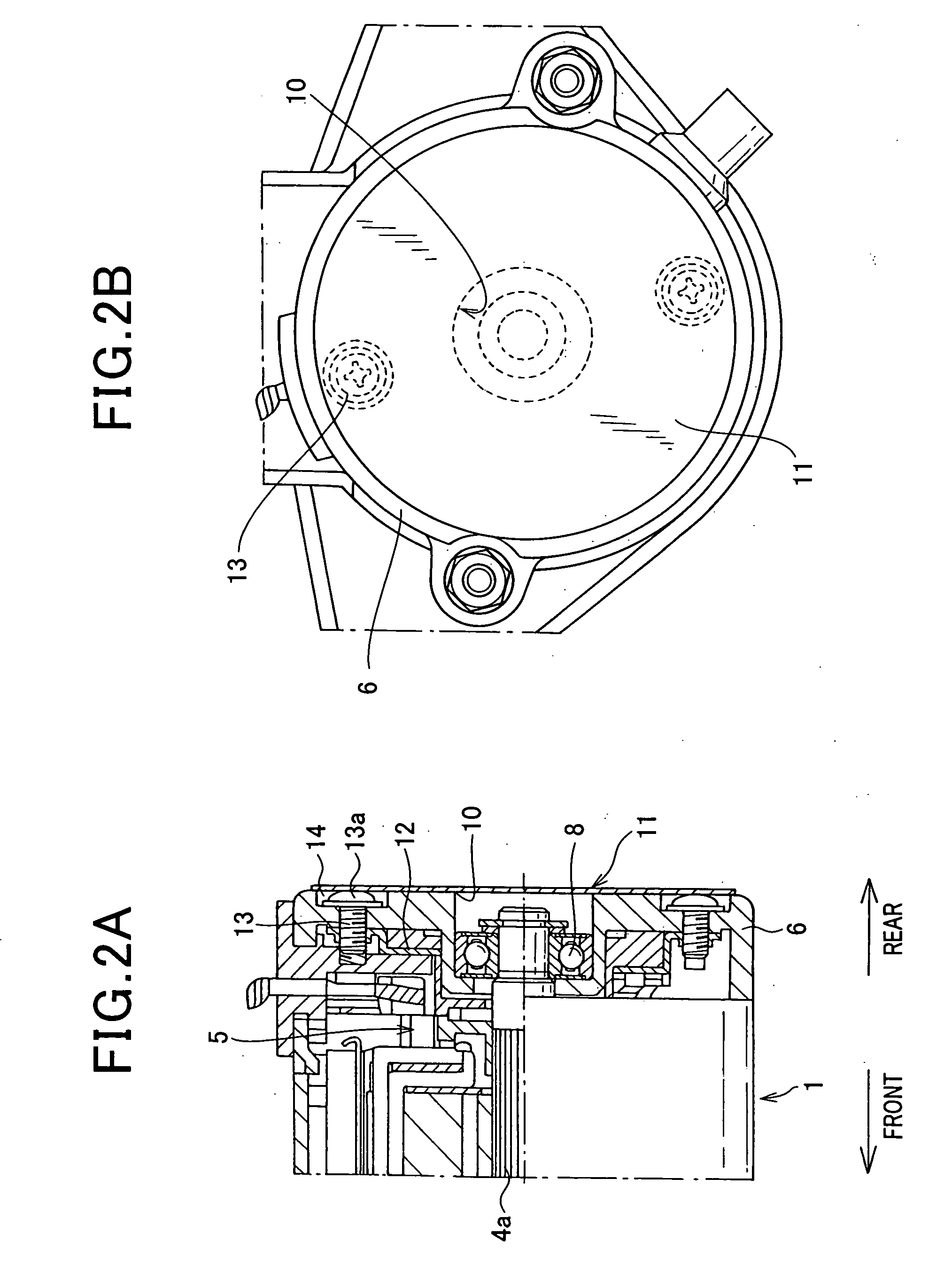
[0053]FIG. 2A shows the overall structure of a starter motor 1 according to the second embodiment of the invention. FIG. 2B shows the shape of a seal plate 11 of the starter motor 1.

[0054]In the starter motor 1, a holder plate 12 for holding the brushes 5 is fixed to the end frame 6 by means of a plurality of (e.g., two in FIG. 2B) screws 13. Further, to sink heads 13a of the screws 13, a plurality of countersunk holes 14 are formed in the end frame 6 to open on the rear end face of the end frame 6.

[0055]Moreover, in the present embodiment, the seal plate 11 is so provided as to hermetically seal the countersunk holes 14 as well as the open end 10 of the bearing box 6a.

[0056]More specifically, in the present embodiment, the seal plate 11 is formed with a sufficiently large diameter with which it is possible for the seal plate 11 to close the countersunk holes 14 as well as the open end 10 of the bearing box 6a. As a matter of course, the diameter of the seal plate...

Example

Third Embodiment

[0058]FIG. 3A shows the shape of a seal plate 11 of a starter motor 1 according to the third embodiment of the invention. FIG. 3B shows the shape of countersunk holes 15 formed in the end frame 6 of the starter motor 1.

[0059]In the starter motor 1, each of the through bolts is located inside of the yoke 3 in the radial direction of the armature shaft 4a. Further, each of the through bolts 7 extents from the rear side of the end frame 6 in the axial direction of the armature shaft 4a, through the end frame 6 and the gap between a circumferentially-adjacent pair of the permanent magnets of the magnetic field system 2, to be fixed to the starter housing.

[0060]Furthermore, to sink heads 7a of the through bolts 7, a plurality of countersunk holes 15 are formed in the end frame 6 to open on the rear end face of the end frame 6, as shown in FIG. 3B.

[0061]Moreover, in the present embodiment, the seal plate 11 is so provided as to hermetically seal the countersunk holes 15 a...


PUM


Abstract

A starter motor is disclosed which includes: 1) a hollow yoke having an open end; 2) a magnetic field system provided on an inner periphery of the yoke; 3) an armature surrounded by the magnetic field system with a predetermined gap therebetween, the armature having an armature shaft; 4) an end frame that closes the open end of the yoke and has a bearing box formed therein, the bearing box being recessed inward of the yoke from an end face of the end frame and having an open end on the end face of the end frame, the bearing box also having a bearing disposed therein to rotatably support an end portion of the armature shaft; and 5) a flexible seal plate that is attached on the end face of the end frame to hermetically seal the open end of the bearing box formed in the end frame.

Description

CROSS-REFERENCE TO RELATED APPLICATION[0001]This application is based on and claims priority from Japanese Patent Application No. 2007-304024, filed on Nov. 26, 2007, the content of which is hereby incorporated by reference in its entirety into this application.BACKGROUND OF THE INVENTION[0002]1. Technical Field of the Invention[0003]The present invention relates generally to starter motors for starting engines. More particularly, the invention relates to a starter motor which includes a seal plate that hermetically seals the open end of a bearing box formed in an end frame of the starter motor.[0004]2. Description of the Related Art[0005]Japanese Patent No. 3575359, an English equivalent of which is U.S. Pat. No. 6,570,283 B2, discloses a starter motor that generates torque for starting an engine of a motor vehicle.[0006]The starter motor includes, as shown in FIG. 4, a cylindrical bearing box 110 formed at the radial center of a discoid end frame 100. A ball bearing 120 is dispose...

Claims


Application Information

Patent Timeline
IPC IPC(8): F02N11/00
CPCF16C19/525F16C33/723F02N2250/08F02N11/00H02K5/10H02K5/1732Y10T74/13
Inventor KAKO, HIROSHIGEANDOH, KAZUHIRO
Owner DENSO CORP
Why Eureka
Try Eureka