
Superconducting magnet system with refrigerator for re-liquifying cryogenic fluid in a tubular conduit

Inactive Publication Date: 2007-05-17
BRUKER BIOSPIN
View PDF8 Cites 2 Cited by
  • Summary
  • Abstract
  • Description
  • Claims
  • Application Information

AI Technical Summary

Benefits of technology

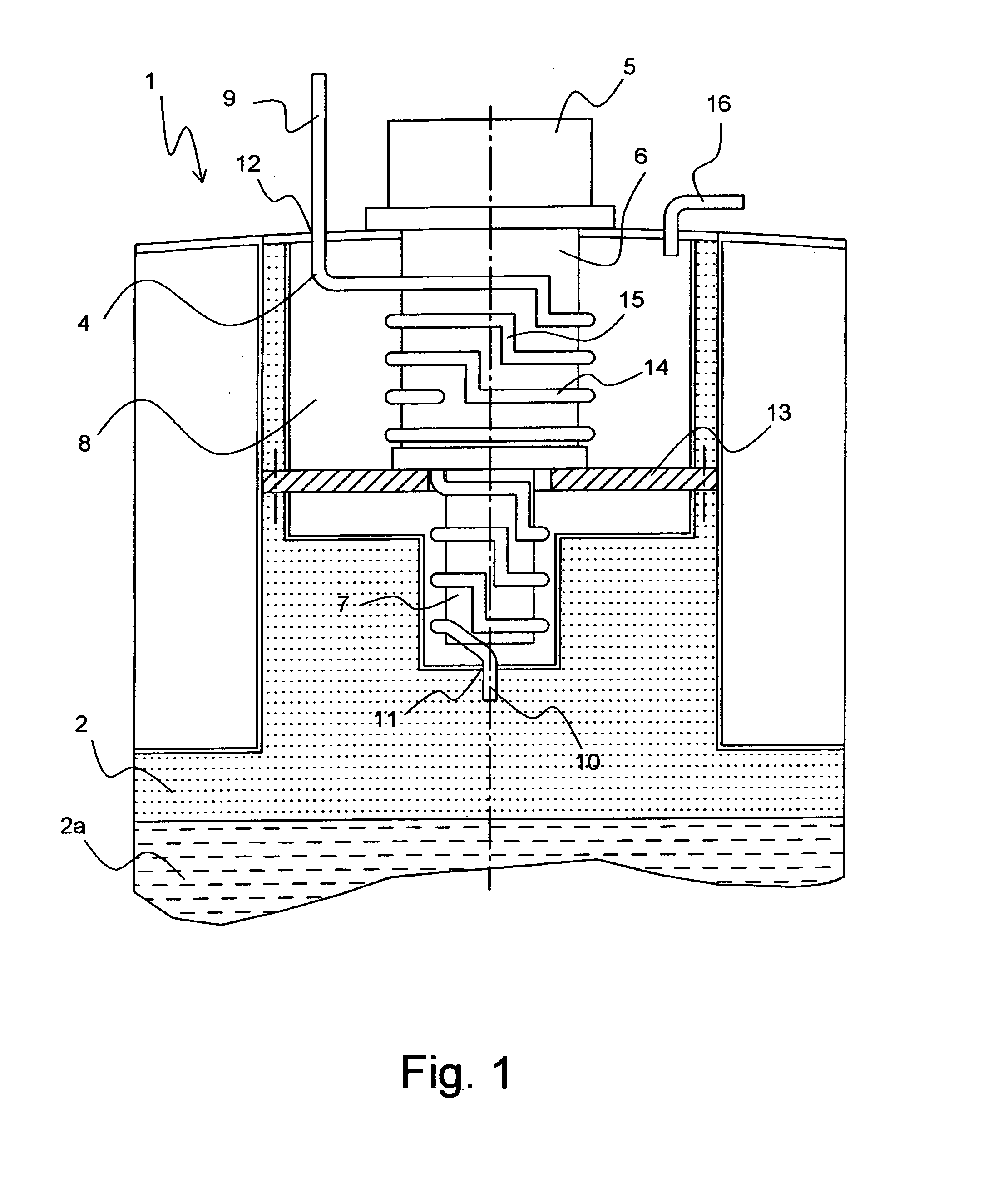
[0008] This object is achieved in accordance with the invention by a superconducting magnet system of the above-mentioned type, which is characterized in that the tubular conduit is rigidly installed in the cryostat. The tubular conduit is therefore not rigidly connected to the refrigerator as in prior art, but may remain in the cryostat in case the refrigerator fails. The opening for the tubular conduit between the vacuum tank of the refrigerator and the cryogenic fluid tank can be optimally sealed, since removal of the tubular conduit is obviated. The invention thereby permits, in particular, rigid weldings between the tubular conduit, the vacuum tank and the cryogenic fluid tank. Moreover, the cryogenic fluid tank need not be opened to exchange the refrigerator. The tubular conduit can be easily kept sealed irrespective of the refrigerator. In order to prevent flow of uncooled cryogenic fluid, a shut-off valve may e.g. be used in a region of the tubular conduit which is at room temperature.
[0009] In one particularly preferred embodiment of the inventive superconducting magnet system, the refrigerator has a first metallic coupling device which provides heat transfer from the tubular conduit to the region of the refrigerator to be cooled. The first coupling device improves thermal conduction between the refrigerator (or its region to be cooled) and the tubular conduit. The first coupling device may either directly contact the tubular conduit or one or more further heat-conducting components which, in turn, are thermally coupled to the tubular conduit.
[0010] In one preferred further development of this embodiment, the first metallic coupling device comprises concentric, disc-like elements. Thermal insulation between the disc-like elements is facilitated to prevent thermal short-circuit along the refrigerator.

Problems solved by technology

However, the superconducting properties only establish themselves at low temperatures.
Due to unavoidable heat input into the cryostat, the cryogenic fluid must normally be regularly refilled.
This process causes downtimes and incurs expense, since the system is disturbed by refilling.
Exchange of the refrigerator simultaneously involves removal of the tubular conduit from an opening between the cryogenic fluid tank and the vacuum container, producing a leakage in the cryogenic fluid tank.
For this reason, expensive coolant can easily escape from the conventional magnet system.

Method used


Image

  • Superconducting magnet system with refrigerator for re-liquifying cryogenic fluid in a tubular conduit
  • Superconducting magnet system with refrigerator for re-liquifying cryogenic fluid in a tubular conduit
  • Superconducting magnet system with refrigerator for re-liquifying cryogenic fluid in a tubular conduit

Examples


Embodiment Construction

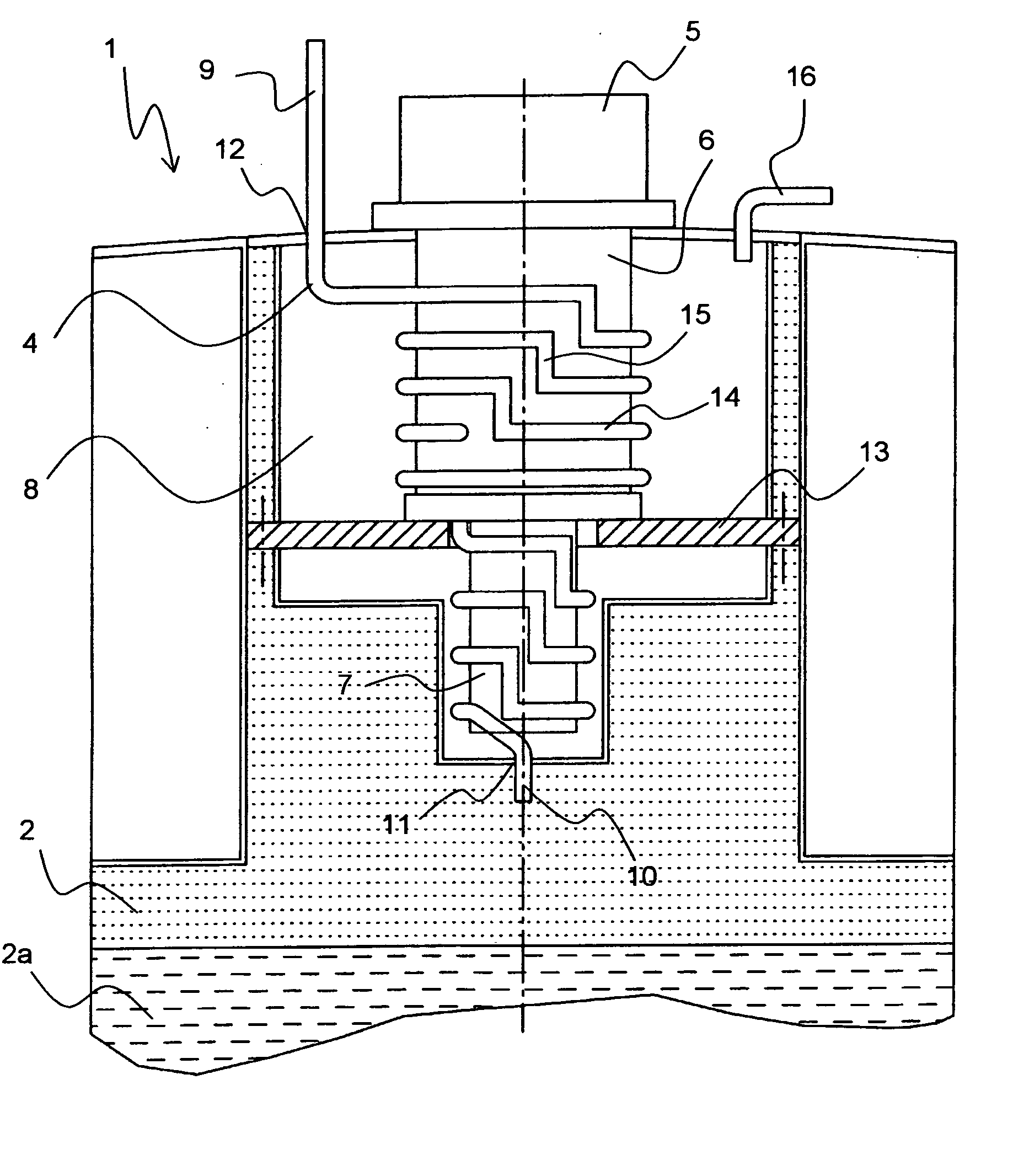
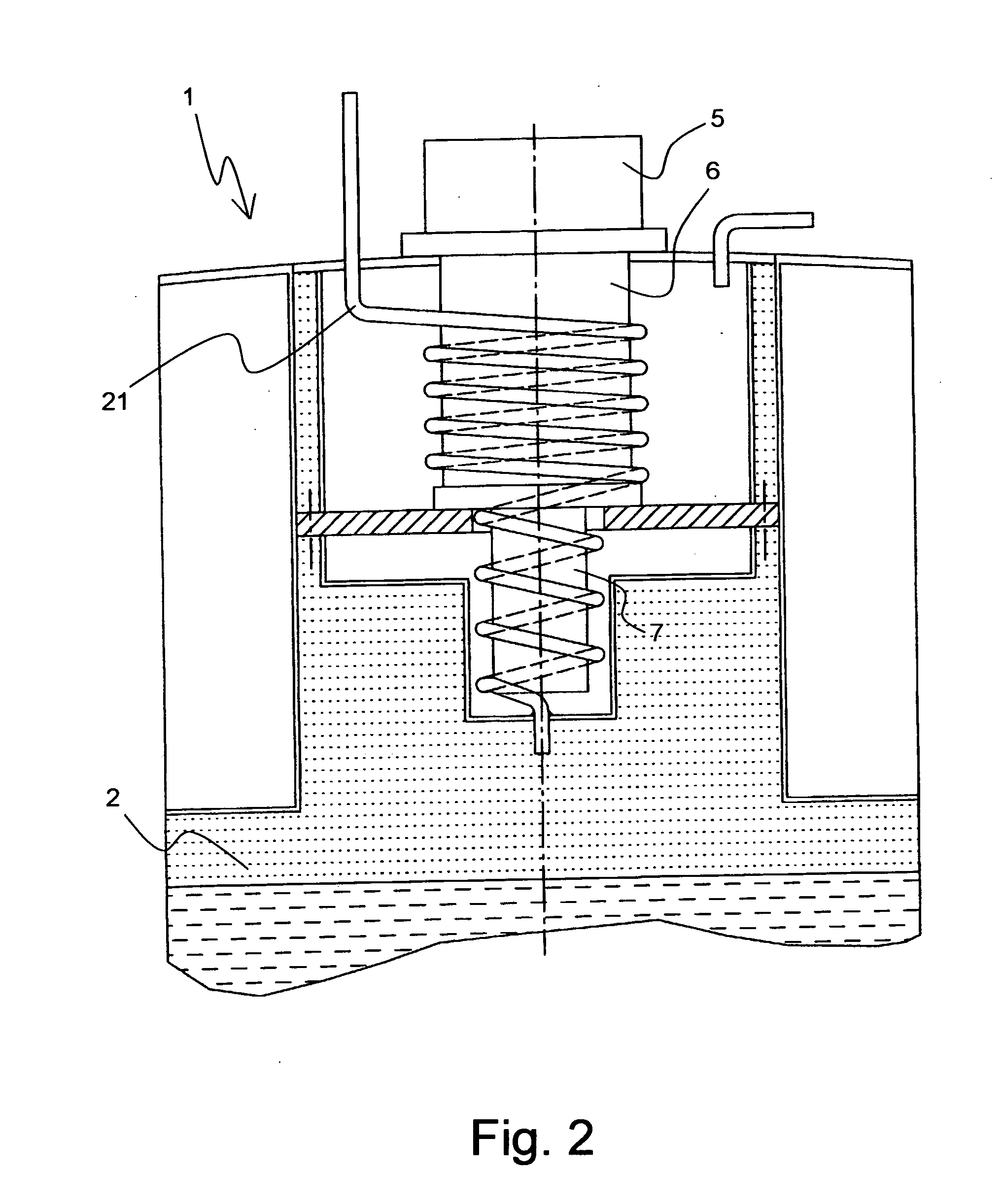
[0035]FIG. 1 schematically shows part of an inventive superconducting magnet system, i.e. the neck tube region of a cryostat 1. The cryostat 1 has a cryogenic fluid tank 2 whose lower region contains liquid cryogenic fluid 2a, i.e. helium. A superconducting magnet coil configuration (also not shown) is located in the region of the liquid cryogenic fluid 2a. Gaseous cryogenic fluid (indicated by dots in FIG. 1) is located above the liquid cryogenic fluid 2a. Cryogenic fluid is permanently pumped to reduce the temperature. The pumped cryogenic fluid is thereby heated outside of the cryogenic fluid tank 2.

[0036] The heated, gaseous cryogenic fluid is cooled and returned, in its liquified state, to the cryogenic fluid tank 2 via a tubular conduit 4. A refrigerator 5 cools the cryogenic fluid. The refrigerator 5 has a first cooling stage 6 and a second, colder cooling stage 7. These two cooling stages 6, 7 are contained in a vacuum container 8 to thermally insulate them from the surroun...


PUM


Abstract

A superconducting magnet system with a superconducting magnet coil system, which is disposed in a cryogenic fluid tank ( 2 ) of a cryostat ( 1 ), and an exchangeable refrigerator ( 5; 31 ) which is operated in a vacuum container ( 8 ) and is provided to re-liquify the cryogenic fluid flowing through a tubular conduit ( 4; 21 ) is characterized in that the tubular conduit ( 4; 21 ) is rigidly installed in the cryostat ( 1 ). The refrigerator reaches its optimum performance during operation in a vacuum, and can be easily exchanged in case of a defect.

Description

[0001] This application claims Paris Convention priority of DE 10 2005 042 834.7 filed Sep. 09, 2005 the complete disclosure of which is hereby incorporated by reference. BACKGROUND OF THE INVENTION [0002] The invention concerns a superconducting magnet system with a superconducting magnet coil system which is disposed in a cryogenic fluid tank of a cryostat, and an exchangeable refrigerator which is operated in a vacuum container to re-liquify the cryogenic fluid that flows through a tubular conduit. [0003] A magnet system of this type is disclosed in Cryogenics 38 (1998), pages 337 to 341. [0004] Superconducting magnet coil systems are used to generate strong magnetic fields. However, the superconducting properties only establish themselves at low temperatures. For this reason, the magnet coil system must be cooled and is therefore disposed in the cryogenic fluid tank of a cryostat. The cryogenic fluid is mainly present in its liquid state, having a maximum temperature which corre...

Claims


Application Information

Patent Timeline
IPC IPC(8): F25B19/00F25B9/00
CPCF17C2270/0527F25B9/10F25B9/14F25B9/145F25B2309/1408F25B2400/17F25D19/006H01F6/04Y02E60/321
Inventor SCHLENGA, KLAUSHANEBECK, CLAUS
Owner BRUKER BIOSPIN
Learn More