Compressor and refrigeration apparatus using the same
- Summary
- Abstract
- Description
- Claims
- Application Information
AI Technical Summary
Benefits of technology
Problems solved by technology
Method used
Image
Examples
first embodiment
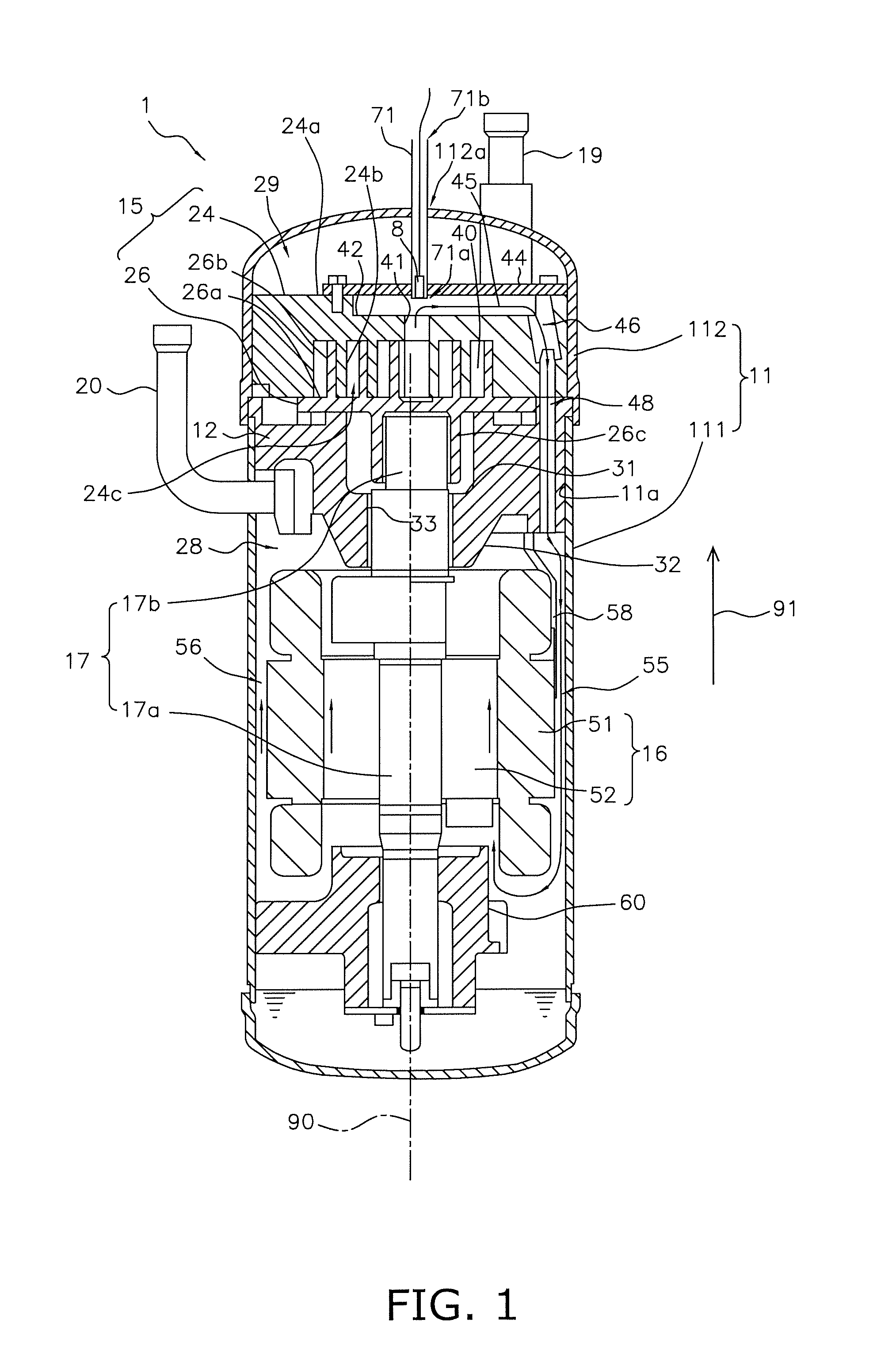
[0069]The aforementioned scroll compressor 1 further includes a pipe 71 (see FIG. 1). The pipe 71 extends from the inside to the outside of the casing 11.
[0070]The pipe 71 includes two ends. One is an end 71a, and the other is an end 71b. The end 71a is a closed end disposed in the space 45 functioning as a refrigerant passage. The end 71b is an opened end disposed outside the casing 11. In FIG. 1, the pipe 71 penetrates through the cover 112 while linearly extending along the direction 91.
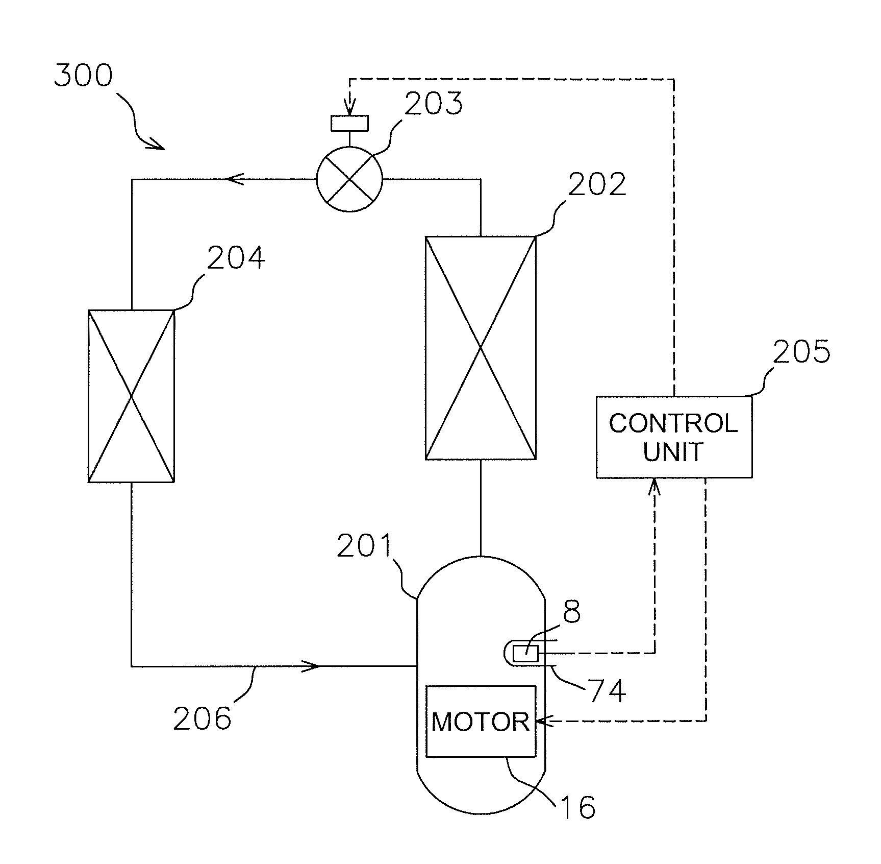
[0071]According to the disposition of the pipe 71, it is easier to seal a pipe, extending from the inside to the outside of a casing, than to seal a wire and the like. Additionally, it is possible to measure temperature of the refrigerant flowing through the space 45 only by inserting a measuring instrument 8 for measuring temperature (hereinafter simply referred to as “measuring instrument”) from the end 71b of the pipe 71. Moreover, even when the measuring instrument 8 is out of order, it is eas...
third embodiment
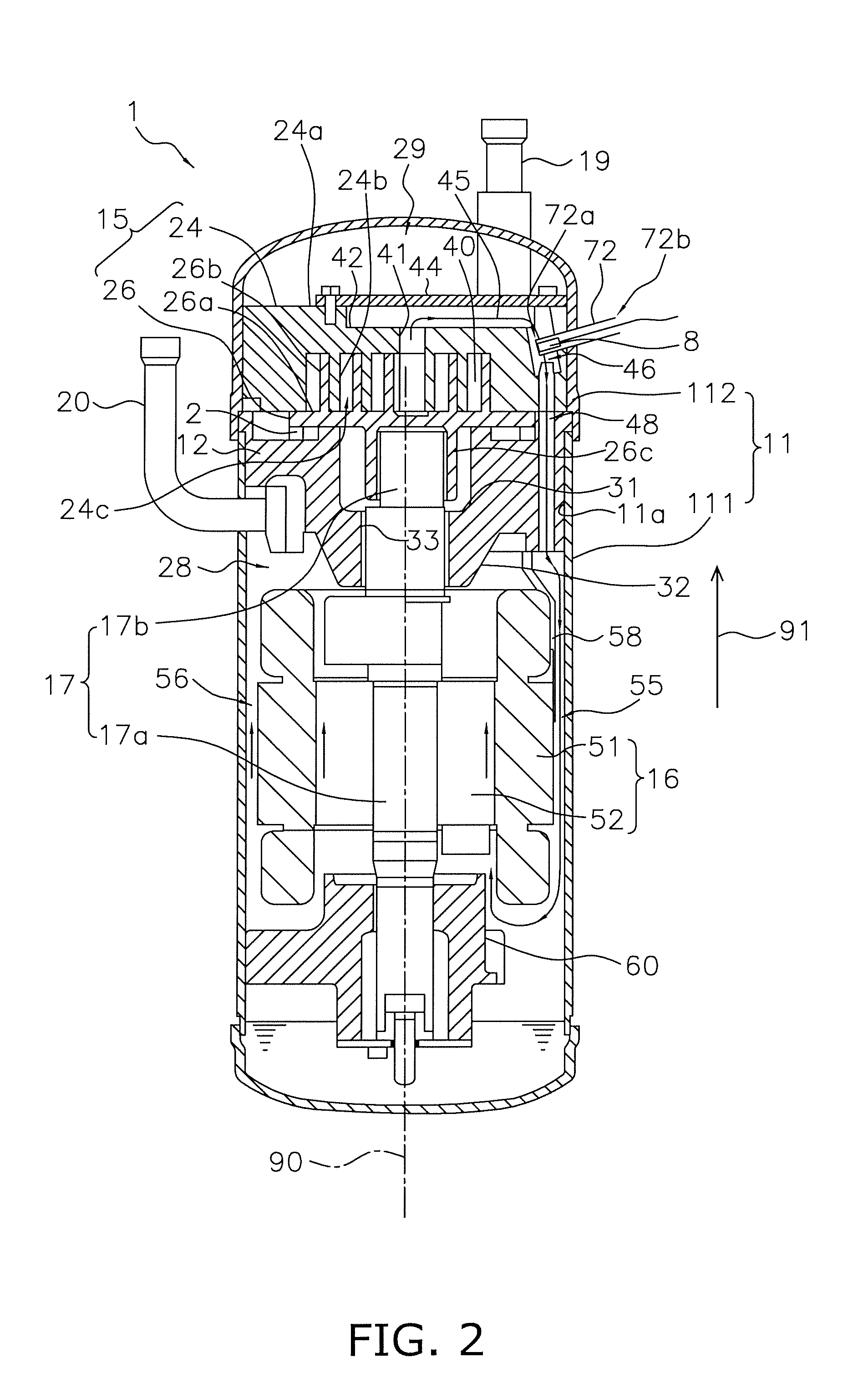
[0081]Each of FIGS. 1 to 3 illustrates the scroll compressor 1 that only each of the pipes 71 to 73 is disposed therein respectively. However, at least any two of the pipes 71 to 73 may be disposed in the same scroll compressor 1, for instance.
Other Embodiment
[0082]The scroll compressor 1 may be provided with a pipe extending to the outside of the casing 11 from the space 28, specifically from the clearance 55 or the clearance 56.
[0083]Temperature of the refrigerant discharged from the discharge port 41 tends to be changed until the refrigerant flows into the space 28. For example, temperature of the motor 16 is low immediately after the scroll compressor 1 is started to be operated. Accordingly, the motor 16 absorbs heat of the refrigerant and refrigerant temperature will be reduced.
[0084]However, when an operation of the scroll compressor 1 is stabilized after it is started to be driven, temperature of the refrigerant flowing through the space 28 will be close to that of the just-...
second embodiment
[0096]201>
[0097]FIG. 6 is a schematic diagram of a scroll compressor 201 according to a second embodiment of the present invention. The scroll compressor 201 illustrated in FIG. 6 has basically the same structure with the scroll compressor 1 illustrated in FIG. 1. When reference numerals in FIG. 6 correspond to those of FIG. 1, the corresponding reference numerals indicate the same component in FIGS. 1 and 6.
[0098]In short, the scroll compressor 201, illustrated in FIG. 6, includes a casing 11, a fix member 12, a compression mechanism 15, a motor 16, a crank shaft 17, an suction pipe 19, a discharge pipe 20, a bearing 60 and a guide plate 58.
[0099]Note in the fix member 12 illustrated in FIG. 6 a recess 31 and a hole 33 are formed by a roller bearing fitted with the fix member 12.
[0100]The motor 16 is disposed below the compression mechanism 15. The motor 16 functions as a driving source of the compression mechanism 15. The motor 16 is configured to rotationally drive the crank shaf...
PUM
 Abstract
Description
Claims
Application Information
 - R&D
- Intellectual Property
- Life Sciences
- Materials
- Tech Scout
- Unparalleled Data Quality
- Higher Quality Content
- 60% Fewer Hallucinations
Browse by: Latest US Patents, China's latest patents, Technical Efficacy Thesaurus, Application Domain, Technology Topic, Popular Technical Reports.
© 2025 PatSnap. All rights reserved.Legal|Privacy policy|Modern Slavery Act Transparency Statement|Sitemap|About US| Contact US: help@patsnap.com


