Needle free medical connector with expanded valve mechanism and method of fluid flow control

a technology of expanding valve mechanism and needle-free connector, which is applied in the direction of couplings, mechanical devices, surgery, etc., can solve the problems of inability to be available, additional steps are undesirable, and the use of additional devices adds costs

Inactive Publication Date: 2006-09-12
CAREFUSION 303 INC
View PDF27 Cites 87 Cited by
  • Summary
  • Abstract
  • Description
  • Claims
  • Application Information

AI Technical Summary

Benefits of technology

[0023]These and other aspects and advantages of the invention will become apparent from the following detailed description and the accompanying drawings, which illustrate by way of example the features of the invention.

Problems solved by technology

However this is an undesirable approach in that another device, i.e. a clamp, is necessary and the care provider must remember to engage the clamp with the tubing.
Furthermore, the use of additional devices adds expense and causes inconvenience in that they may not be available at the time needed.
Additional steps are also undesirable in that most care providers are very busy already and would therefore naturally prefer to reduce the number of steps in providing effective care to patients rather than increase the number.
In another approach, one that disadvantageously also increases the number of steps in the administration of medical fluids, the operator continually injects fluid into the connector from the male device while the male device is being disengaged from the connector.
However, this approach is also undesirable in that not only does it add a step but may require some skill in successfully carrying out the procedure.
A disadvantage of typical connectors having an internal cannula or spike is a lower fluid-flow rate caused by the small lumen in the cannula or spike.
Additionally, it has been noted that with the connector design having a fixedly-mounted internal spike and a movable septum that is pierced by that spike to permit fluid flow, such pierced septum may be damaged with multiple uses and a leaking connector may result.
However, the valve mechanism is relatively complex with a leaf spring being incorporated into a flexible member which adds some manufacturing concerns as well as at least one additional part; i.e., the leaf spring.
Manufacturing concerns and additional parts can tend to cause expenses to rise, an undesirable effect in the health care industry today where manufacturers strive to provide effective products at lower costs.
Further, the reservoir-type system does not permit continuous flow through the entire expandable flexible body section.

Method used


Image

  • Needle free medical connector with expanded valve mechanism and method of fluid flow control
  • Needle free medical connector with expanded valve mechanism and method of fluid flow control
  • Needle free medical connector with expanded valve mechanism and method of fluid flow control

Examples


Embodiment Construction

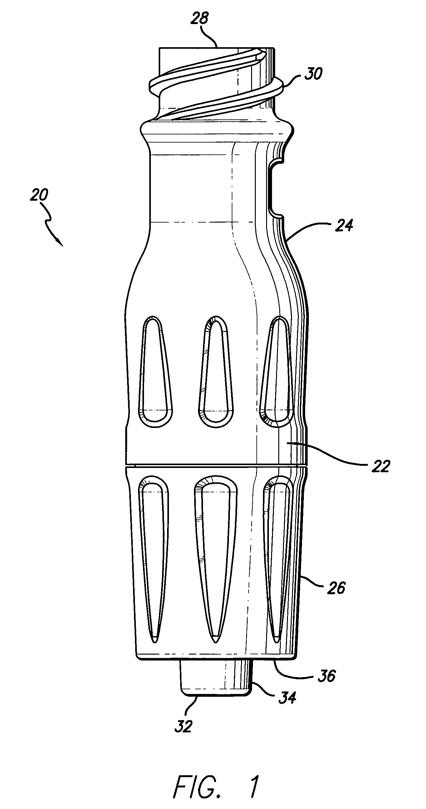
[0038]Referring now in detail to the drawings in which like numerals refer to like or corresponding elements among the several figures, there is illustrated in FIG. 1 a side external view of a medical connector that includes various aspects of the present invention. The particular connector configuration exemplified in the figures is for illustration purposes only. The connector may be embodied in different configurations including, but not limited to, Y-connectors, J-loops, T-connectors, tri-connectors, PRN adapters, slip Luers, tubing engagement devices, access pins, vial adapters, blood tube adapters, bag access pins, vented adapters, and others. The drawings are for illustration purposes only.

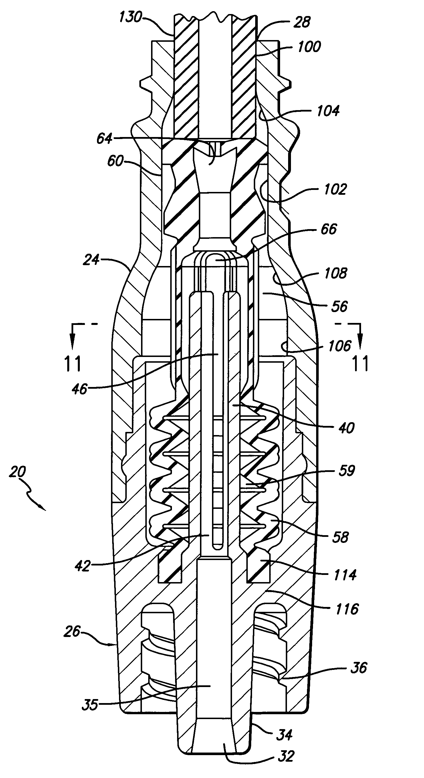
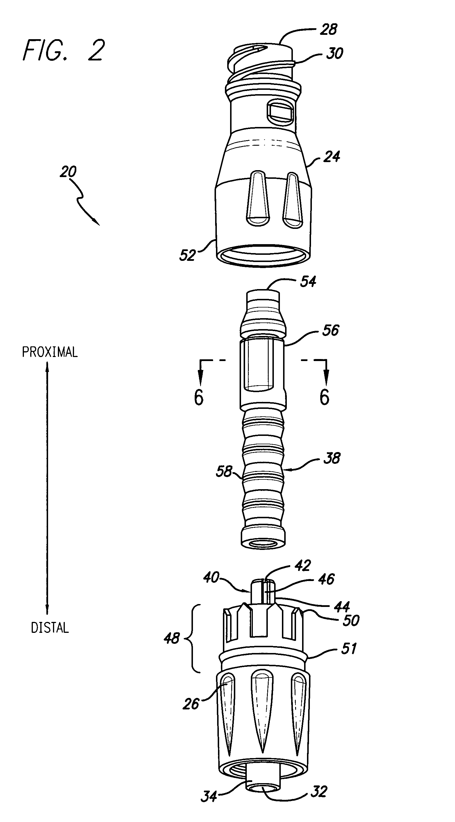
[0039]FIG. 1 presents an embodiment of a medical connector 20 having a housing 22 that is formed of an upper housing portion 24 and a lower housing portion 26. The upper housing portion 24 has a first port 28, that in this case is a female Luer connector port with thread elements 30 located...


PUM


Abstract

A needle free medical connector includes a housing with a first port and a second port. The connector also includes a piston element defining a fluid passageway between the first and second ports. The piston element is movable between flow and non-flow positions. The piston element has a compressible section having a variable inner width that forms a part of the flow path through the connector. As the piston is compressed to the flow position, the compressible section self-expands in width thereby maintaining or increasing the volume of the fluid passageway through the connector. The compressible section has a configuration permitting the continuous flow of fluid through its entirety.

Description

[0001]This is a continuation of application Ser. No. 09 / 998,383 filed on Nov. 29, 2001, now U.S. Pat. No. 6,802,490.INCORPORATION BY REFERENCE[0002]We hereby incorporate by reference U.S. Pat. No. 5,676,346 to Leinsing.BACKGROUND[0003]The invention relates generally to medical connectors of the type used in the handling and administration of parenteral fluids, and more particularly, to a needle free connector employing a valve mechanism that compensates for negative fluid displacement, i. e., drawing fluid into the connector, as the connector returns to its unaccessed state from an accessed state.[0004]Within this specification the terms, “negative-bolus effect,”“positive-bolus effect,” and “no-bolus effect” are used to describe the operating characteristics of medical connectors as the connector returns to its unaccessed state from an accessed state. “Negative-bolus” effect describes the condition during which fluid is drawn into the connector as the connector returns to its unacce...

Claims


Application Information

Patent Timeline
Patent Type & Authority Patents(United States)
IPC IPC(8): F16L37/28A61M39/02A61M39/00F16K51/00A61M39/26
CPCA61M39/26A61M2039/262Y10S604/905A61M2039/266A61M2039/263A61M2039/267
Inventor LEINSING, KARL R.MOSLER, THEODORE J.
Owner CAREFUSION 303 INC
Why Eureka
Try Eureka