
Needle-free medical connector

a technology of medical connectors and needles, applied in the direction of valve arrangements, couplings, intravenous devices, etc., can solve the problem of lack of closed seals

Inactive Publication Date: 2009-03-05
THORNE CONSULTING & INTPROP
View PDF15 Cites 41 Cited by
  • Summary
  • Abstract
  • Description
  • Claims
  • Application Information

AI Technical Summary

Benefits of technology

The invention is a needle-free connector that allows for fluid communication without the use of needles. The connector has a housing with an elongated hollow cylindrical shape, with parts securely affixed together about a central axis. The housing has a first port for receiving a blunt cannula, and a second port for communication with an external conduit. The connector has a displaceable valved component that is designed to control fluid communication. The valved component has an externally facing valve that is normally closed but can be opened when the blunt cannula is inserted. The valved component has a hollow post with a through hole that allows for sealing with the blunt cannula in a closed state. The connector is made from synthetic resinous materials such as polypropylene or polycarbonate. The connector has a low manufacturing cost, is sterilizable, and has a low dead space. The connector is compatible with standard luer fittings and can be cleaned by swabbing or other cleaning methods. The connector has a self-closing valve that is opened upon displacement of the blunt cannula and self-closes upon retraction of the cannula. The connector has a flow path within the displaceable component that is greater in volume when the valve is open than when the valve is closed.

Problems solved by technology

Concern for such compressible plugs is possible reflux which may result when the plug is permitted to decompress when the luer fitting is removed and a lack of a closed seal about an inserted cannula tip.

Method used


Image

  • Needle-free medical connector
  • Needle-free medical connector
  • Needle-free medical connector

Examples


Embodiment Construction

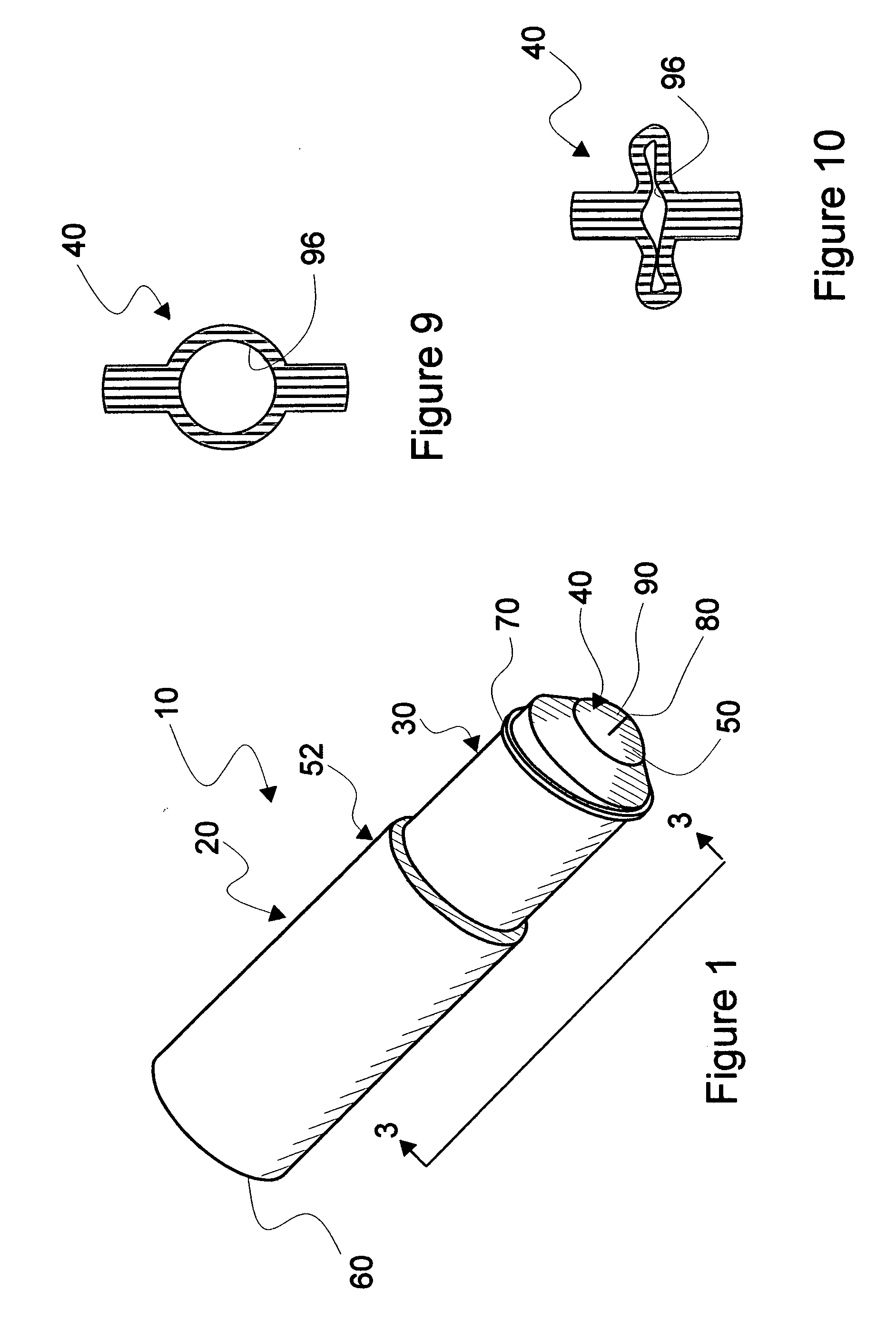
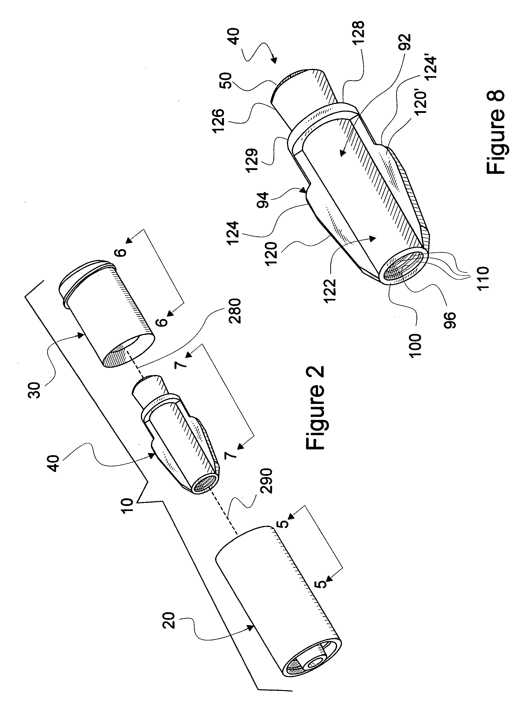
[0049]In this description, the term proximal is used to indicate the segment of the device normally closest to the object of the sentence describing its position. The term distal refers to the other end. Reference is now made to the embodiments illustrated in FIGS. 1-12 wherein like numerals are used to designate like parts throughout. Primes of numbers refer to parts which are similar to parts having like numbers but are not identical with those parts in form or function.

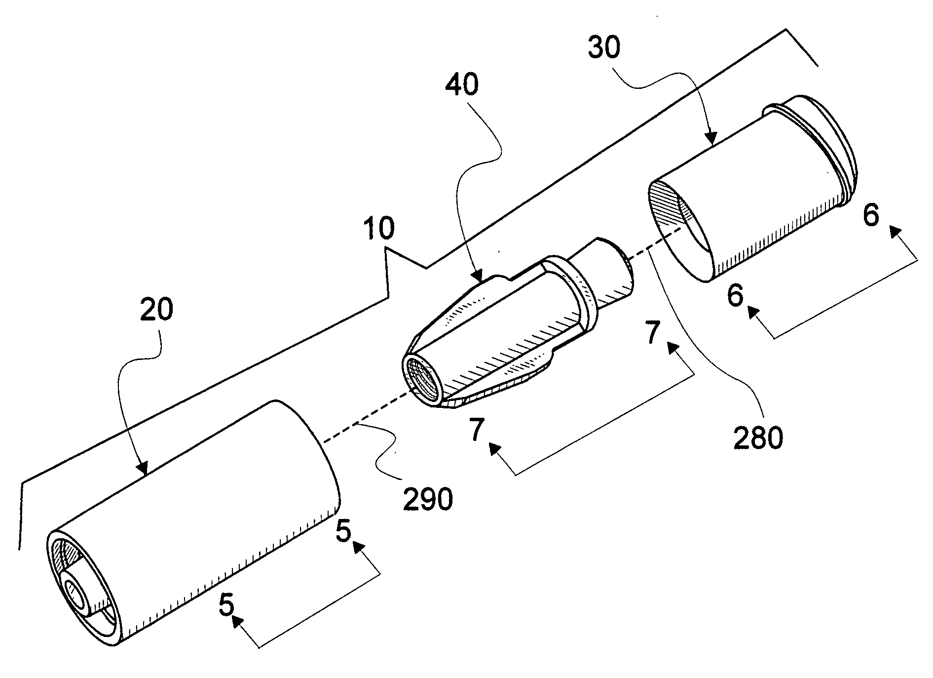
[0050]As seen in FIG. 1, needle-free connector 10 according to the present invention is generally made from three parts, a line or catheter communicating section 20, a male luer accessible section 30 and a displaceable component 40 where a domed valve portion 50 is seen extending outward from section 30. Section 30 is securely affixed to section 20 by adhesion, ultrasonic welding or other joining method as is commonly practiced in the medical manufacturing industry to form a housing 52 for component 40. On an end 6...


PUM


Abstract

A needleless connector for controllably permitting fluid communication between a cannula and a port usually associated with a patient catheter or line. The connector is made from three parts, two of which form an elongated housing for a valve part. The valve part comprises a domed slit valve which is in a closed state before a cannula is inserted into the housing. Insertion of the cannula inverts the dome valve to open a slit permitting fluid communication there through. Insertion of the cannula also displaces the valve part about and along a post internally disposed in the housing. Assembled, the valve part is initially disposed about the post in a compressive sealed relationship to form a secure pathway therebetween. The post is shaped to store greater energy by stretching portions of the valve part as the valve part is displaced therealong. Upon removal of the cannula, stored energy is released from the stretched portion of the valve part to return the valve part to an original state, presenting a closed and cleanable surface to a user.

Description

CONTINUATION-IN-PART[0001]This Application for United States Patent is a Continuation-in-Part of U.S. patent application Ser. No. 11 / 899,254 titled MULTI-CHAMBER SEQUENTIALLY DISPENSING SYRINGE and filed Sep. 5, 2007 by Gale H. Thorne, Jr. (Thorne, Jr.).BACKGROUND[0002]A variety of needle-free medical connectors are currently commercially available. Such connectors are generally used in handling and administering parenteral fluids, especially fluids associated with extension sets and patient catheters. These connectors are more specifically designed to interface, on a fluid dispensing and acquiring end, with a first, usually female, luer fitting, thereby to interface with fittings such as those commonly found on conventional syringes. On the other end, often, interface is through another luer fitting to provide a needleless communicating link to a catheter or an extension set affixed to a catheter.[0003]An example of a needle-free connector is disclosed in U.S. Pat. No. 7,244,249 B2...

Claims


Application Information

Patent Timeline
Patent Type & Authority Applications(United States)
IPC IPC(8): F16K51/00
CPCA61M39/26A61M2039/263A61M2039/261A61M2039/267
Inventor THORNE, JR., GALE H.THORNE, GALE H.
Owner THORNE CONSULTING & INTPROP
Learn More