Wheel made of lightweight alloy

A light alloy and wheel technology, applied in the field of light alloy wheels, can solve the problems of insufficient lateral rigidity, increased rim rigidity, and insufficient longitudinal rigidity, and achieve the effects of increased rigidity, increased longitudinal rigidity, and improved lateral rigidity

Inactive Publication Date: 2012-11-28
WASHI KOSAN
View PDF3 Cites 9 Cited by
  • Summary
  • Abstract
  • Description
  • Claims
  • Application Information

AI Technical Summary

Problems solved by technology

[0015] However, since the automobile wheel disclosed in Patent Document 1 has a U-shaped arm, although the lateral rigidity is definitely improved, its longitudinal rigidity is insufficient.
In addition, although this document also discloses an automobile wheel with a W-shaped arm, since the part inside the connecting part with the bead seat part is too large, it may collide with the suspension, and it is composed of a composite material of synthetic resin. so not practical
[0016] In the rim for a wheel disclosed in Patent Document 2, since it cannot be integrally formed even if it is bent, it is difficult to say that the rigidity of the rim is sufficiently improved.
[0017] The vehicle wheel disclosed in Patent Document 3 has excellent longitudinal rigidity, but insufficient lateral rigidity.

Method used


Image

  • Wheel made of lightweight alloy
  • Wheel made of lightweight alloy
  • Wheel made of lightweight alloy

Examples


no. 1 Embodiment approach

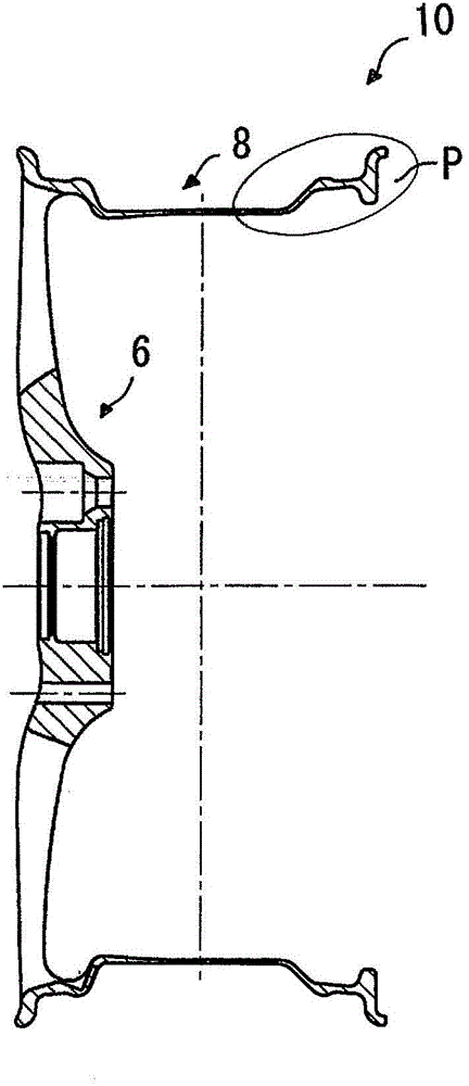
[0064] figure 1 It is a sectional view showing the light alloy wheel of the first embodiment.

[0065] Such as figure 1 As shown, the light alloy wheel 10 of the first embodiment includes a spoke portion 6 , an inner rim portion 8 erected around the spoke portion 6 , and an outer rim portion erected around the spoke portion 6 .

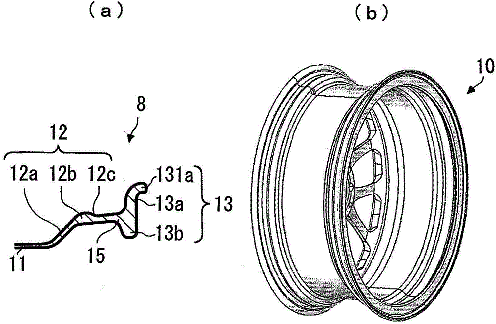
[0066] figure 2 (a) is shown figure 1 (b) is a perspective view showing the light alloy wheel of the first embodiment.

[0067] Such as figure 2 As shown in (a) and (b), in the light alloy wheel 10 of the first embodiment, the inner rim portion 8 includes a rim well portion 11 vertically erected around the spoke portion 6, and the rim well portion. 11 a continuous rim middle portion 12, and an inner rim flange portion 13 connected to a connecting portion 15 at the front edge of the rim middle portion 12.

[0068] The rim intermediate portion 12 is composed of an inclined connection portion 12a, a protruding peak portion 12b provided on the con...

no. 2 Embodiment approach

[0085] The light alloy wheel of the second embodiment is the same as the light alloy wheel 10 of the first embodiment except for the shape of the inner rim flange.

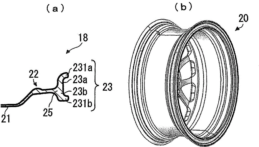
[0086] image 3 (a) is an enlarged sectional view showing the inner rim portion of the light alloy wheel of the second embodiment, and (b) is a perspective view showing the light alloy wheel of the second embodiment.

[0087] Such as image 3 As shown in (a) and (b), in the light alloy wheel 20 according to the second embodiment, the inner rim portion 18 is provided with a rim well portion 21 vertically erected around the spoke portion, and is continuous with the rim well portion 21 The rim middle part 22, and the inner rim flange part 23 connected with the connecting part 25 at the front of the rim middle part 22.

[0088] The inner rim flange portion 23 has an outer peripheral flange 23a extending outward from the connecting portion 25, an outer peripheral flange curved portion 231a formed by bending the perip...

no. 3 Embodiment approach

[0092] The light alloy wheel of the third embodiment has a configuration in which the ribs for rim wells are arranged in the light alloy wheel 10 of the first embodiment.

[0093] Figure 4 (a) is an enlarged sectional view showing the inner rim portion of the light alloy wheel of the third embodiment, and (b) is a perspective view showing the light alloy wheel of the third embodiment.

[0094] Such as Figure 4 As shown in (a) and (b), in the light alloy wheel 30 according to the third embodiment, the inner rim portion 8 is provided with the rim well rib 80 in the rim well portion 11 .

[0095] The rim well rib 80 is connected to the connecting portion 12 a and the outer rim portion 34 .

[0096] In the light alloy wheel 30 according to the third embodiment, since the ribs 80 for the rim well are arranged, the longitudinal rigidity of the rim well portion 11 can be further improved, and at the same time, it is possible to suppress the friction between the spoke side and the...


PUM

PropertyMeasurementUnit
thicknessaaaaaaaaaa

Abstract

Disclosed is a wheel made of lightweight alloy having superior rigidity in the vertical and horizontal directions. A wheel made of lightweight alloy (10) for use with vehicles comprises a disc portion (6); and an inner rim portion (8) arranged in a standing state upon the rim of the disc portion (6). The inner rim portion (8) further comprises a well portion (11) arranged in a standing state vertically upon the rim of the disc portion (6); a rim center portion (12) that is serially connected to the well portion (11); and an inner rim flange portion (13) that is connected to a connecting portion (15) of the leading edge of the rim center portion (12). The inner rim flange portion (13) further comprises a perimeter flange (13a), which extends outward from the connecting portion (15); and an inner circumference flange (13b), which extends inward from the connecting portion (15). The edge of the perimeter flange (13a) curves in the axial direction.

Description

technical field [0001] The invention relates to a light alloy wheel which strengthens the rim and improves the rigidity. Background technique [0002] Vehicles traveling on the road generally have metal wheels on which tires are mounted and which support the tires. [0003] In recent years, wheels that are as light as possible and offer great designability have been favored. Especially in passenger vehicles, the diameter of wheels is increasing day by day in order to reduce vibration during driving and improve maneuverability. [0004] However, as the diameter of the wheel increases, the substantially cylindrical inner rim tends to warp. [0005] For such defects, some studies have proposed a method of strengthening the inner rim flange of the inner rim. [0006] For example, there is known an automobile wheel whose rim has a bead holding flange made of a composite material having a U-shaped cavity extending along the entire circumference of the rim (for example, refer to...

Claims


Application Information

Patent Timeline
Patent Type & Authority Applications(China)
IPC IPC(8): B60B21/02B60B21/00
CPCB60B21/026B60B3/02B60Y2200/11B60B21/106B60B2900/111B60B2360/104B60B1/06Y02T10/86
Inventor 小野光太郎
Owner WASHI KOSAN
Why Eureka
Try Eureka