Tray and dolly assembly

a dolly and assembly technology, applied in the direction of trays, rigid containers, transportation and packaging, etc., can solve the problems of slipping or falling of the trays, affecting the translation or rotation of the trays, and affecting the appearance of the trays

Inactive Publication Date: 2006-09-12
REHRIG PACIFIC CO INC
View PDF23 Cites 37 Cited by
  • Summary
  • Abstract
  • Description
  • Claims
  • Application Information

AI Technical Summary

Benefits of technology

[0007]It is, therefore, an object of the present invention to provide an improved dolly, and an improved tray and dolly assembly in which the dolly includes one or more features that compliment the tray features to provide an overall enhanced tray and dolly assembly.
[0008]In carrying out the above object, a tray and dolly assembly is provided. The tray and dolly assembly comprises a dolly and a tray. The dolly has a floor with upper and lower surfaces. The floor has a plurality of protruding members extending upwardly from the floor upper surface. The tray has a floor with upper and lower surfaces. The tray floor has a plurality of openings. The tray further has a pair of opposed side walls. When the tray floor is received on the dolly floor, the plurality of protruding members extends into the plurality of openings to interlock the tray with respect to the dolly. Advantageously, the upwardly extending protruding members on the dolly floor cooperate with the openings in the tray floor to provide improved interlocking of the tray with the dolly.
[0017]The advantages associated with embodiments of the present invention are numerous. Embodiments of the present invention provide various embodiments for a dolly and various embodiments for a tray and dolly assembly that improve over existing dollies and existing tray and dolly assemblies. Advantageously, embodiments of the present invention provide enhanced features on the dolly that, when a tray is placed in the dolly, cooperate with features on the tray to interlock the dolly and the tray. Suitable implementations have a feature or multiple features on the dolly that prevent the tray from slipping off of the dolly, and impede translation or rotation of the tray with respect to the dolly when the tray is received on the dolly.

Problems solved by technology

Although improved trays such as that shown in U.S. Pat. No. 5,881,902 have been developed, existing dollies are still rather plain and generally lack features.
That is, with some existing dollies, trays may sometimes slip off of the dolly or become misaligned.

Method used


Image

  • Tray and dolly assembly
  • Tray and dolly assembly
  • Tray and dolly assembly

Examples


Embodiment Construction

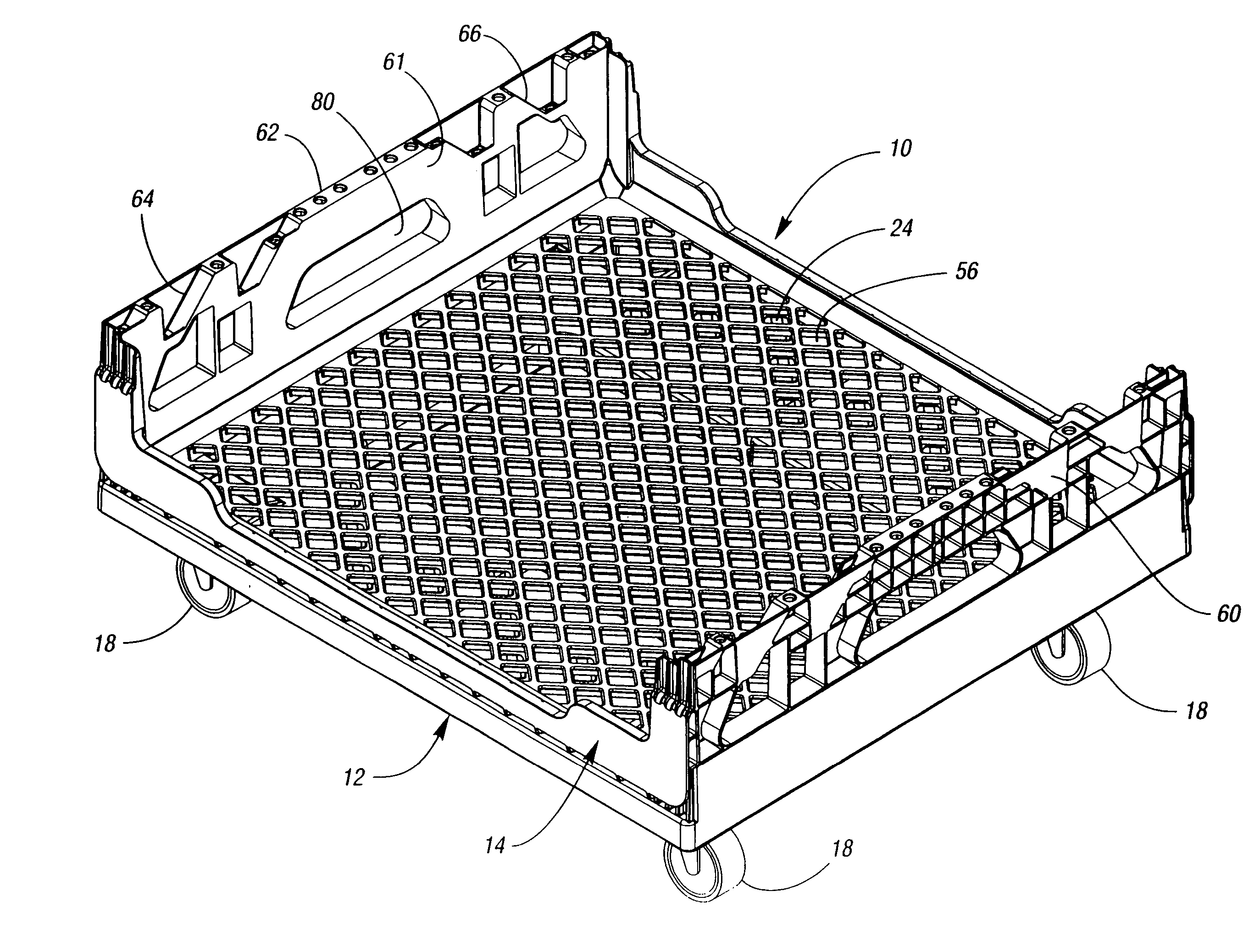
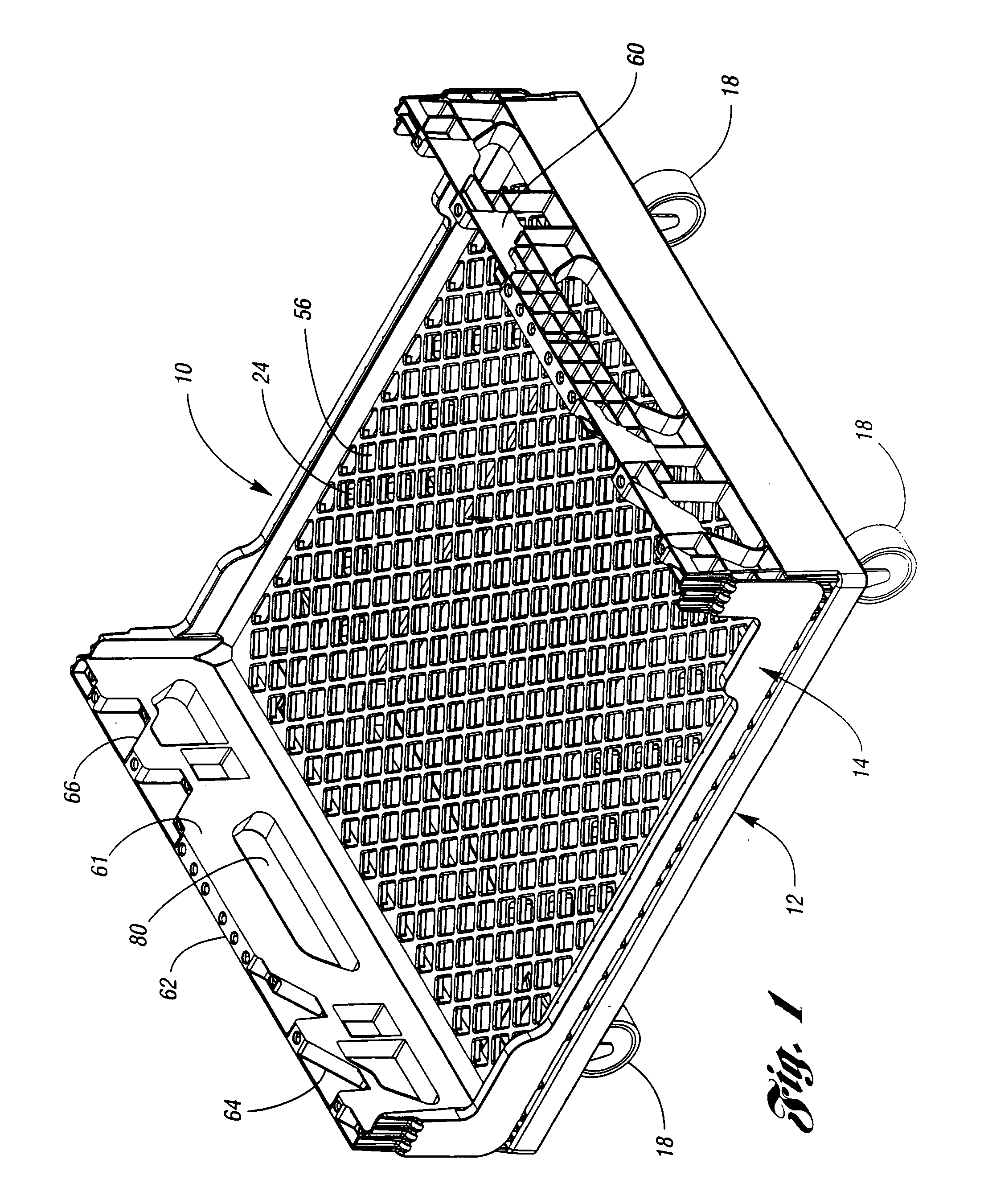
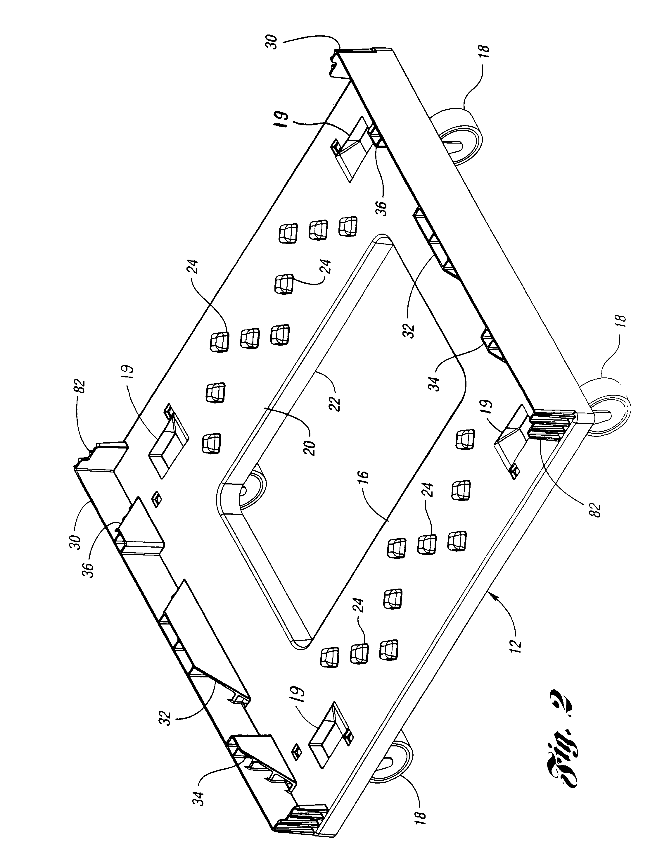
[0027]With reference to FIG. 1, a tray and dolly assembly according to the present invention is generally indicated at 10. The dolly is generally indicated at 12, while the tray is generally indicated at 14. With reference to FIGS. 1–5, and as best shown in FIGS. 2 and 3, dolly 12 has a floor 16. Floor 16 has an upper surface 20 and a lower surface 22. A plurality of bumps or protruding members 24 extend upwardly from upper surface 20. Dolly 12 further has a pair of opposed side walls 30. Each side wall 30 has a locking portion. The preferred locking portion for side wall 30 is composed of inwardly extending locking portions 32, 34, 36. Dolly 12 is preferably rectangular in shape and has four corners. A plurality of casters, such as four casters 18, supports the dolly floor with a caster 18 located proximate each corner of dolly floor 16. As best shown in FIG. 4, tray 14 has a floor 50. Tray floor 50 has an upper surface 52 and a lower surface 54. Tray floor 50 has a plurality of op...


PUM


Abstract

A dolly and a tray and dolly assembly are provided. The dolly has a floor with upper and lower surfaces and with one or more features such that when the tray floor is received on the dolly floor, the feature interlocks the tray with the dolly. One feature is a plurality of protruding members extending upwardly from the dolly floor upper surface into openings in the tray floor to interlock the tray with the dolly. Another features is the presence of dolly side wall locking portions configured to abut and mate with corresponding tray side wall bottom locking portions on the tray to interlock the dolly with the tray.

Description

CROSS-REFERENCE TO RELATED APPLICATION[0001]This application is a continuation of application U.S. Ser. No. 10 / 621,974, filed Jul. 17, 2003, now U.S. Pat. No. 6,857,642 which is a continuation of U.S. Ser. No. 09 / 839,018, filed Apr. 20, 2001, now U.S. Pat. No. 6,607,199BACKGROUND OF THE INVENTION[0002]1. Field of the Invention[0003]The present invention relates to a tray and dolly assembly.[0004]2. Background Art[0005]A typical dolly has a generally flat floor which may be supported by casters. A tray may then be placed on the dolly. Sometimes, the tray is configured to allow multiple trays to be stacked on top of each other with the bottom tray resting on the dolly. These stackable trays are suitable for many purposes, including use as a multi-level bakery tray. An existing multi-level bakery tray is disclosed in U.S. Pat. No. 5,881,902 issued to Ackerman which is hereby incorporated by reference in its entirety. U.S. Pat. No. 5,881,902 describes a multi-level bakery tray with a ge...

Claims


Application Information

Patent Timeline
Patent Type & Authority Patents(United States)
IPC IPC(8): B62B3/02B62B3/00B62B3/16B62B5/00
CPCB62B3/006B62B3/16B62B5/0083B62B2501/065B62B2202/12
Inventor GRUBER, ROBERT V.
Owner REHRIG PACIFIC CO INC
Why Eureka
Try Eureka