Variable capacity rotary compressor

a rotary compressor and variable capacity technology, applied in the direction of positive displacement liquid engines, piston pumps, liquid fuel engines, etc., can solve the problems of wasting energy, changing the capacity of the rotary compressor, and generating noise, so as to increase durability and prevent noise generation

Inactive Publication Date: 2006-09-12
SAMSUNG ELECTRONICS CO LTD
View PDF8 Cites 27 Cited by
  • Summary
  • Abstract
  • Description
  • Claims
  • Application Information

AI Technical Summary

Benefits of technology

[0010]Accordingly, it is an aspect of the present invention to provide a variable capacity rotary compressor, which is constructed so that a compression operation is executed in either of two compression chambers having different capacities by an eccentric unit mounted to a rotating shaft, thus varying a compression capacity as desired.
[0011]It is another aspect of the present invention to provide a variable capacity rotary compressor, which is designed to prevent the eccentric unit from slipping during a compression operation, thus preventing noise from being generated and increasing durability.

Problems solved by technology

However, the conventional rotary compressor has a problem in that the rotary compressor is fixed in a compression capacity thereof, so that it is impossible to vary the compression capacity according to a difference between an environmental temperature and a preset reference temperature.
However, it is impossible to change the capacity of the rotary compressor according to the difference between the environmental temperature and the preset reference temperature, so that the conventional rotary compressor does not efficiently cope with a variance in temperature, thus leading to a waste of energy.

Method used


Image

  • Variable capacity rotary compressor
  • Variable capacity rotary compressor
  • Variable capacity rotary compressor

Examples


Embodiment Construction

[0033]Reference will now be made in detail to the present preferred embodiments of the present invention, examples of which are illustrated in the accompanying drawings, wherein like reference numerals refer to like elements throughout.

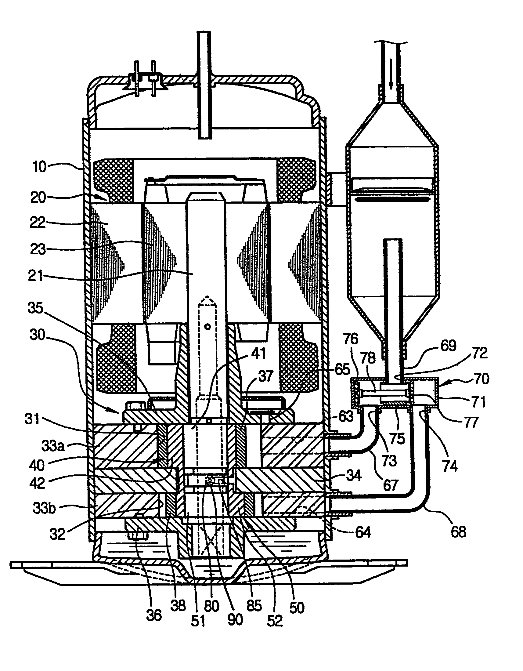
[0034]As illustrated in FIG. 1, a variable capacity rotary compressor, according to the present invention includes a hermetic casing 10. A drive unit 20 is installed in the casing 10 to be placed on an upper portion of the casing 10, and generates a rotating force. A compressing unit 30 is installed in the casing 10 to be placed on a lower portion of the casing 10, and is connected to the drive unit 20 through the rotating shaft 21. The drive unit 20 includes a cylindrical stator 22, and a rotor 23. The stator 22 is mounted to an inner surface of the casing 10. The rotor 23 is rotatably and concentrically set in the stator 22, and is mounted to the rotating shaft 21 which is placed at a center of the casing 10. The drive unit 20 rotates the rotating s...


PUM


Abstract

A variable capacity rotary compressor is designed to prevent eccentric bushes from slipping during a compression operation, thus preventing noise from being generated and increasing durability. The compressor includes a housing to define two compression chambers having different capacities therein. A rotating shaft is rotated in the compression chambers. Two eccentric cams are mounted to the rotating shaft. Two eccentric bushes are rotatably fitted over the eccentric cams. Two rollers are rotatably fitted over the eccentric bushes. Two vanes are installed in the compression chambers to be reciprocated in a radial direction of the rotating shaft. A cylindrical connecting part integrally connects the eccentric bushes to each other, with a locking slot being provided around the connecting part. A locking pin is mounted to the rotating shaft to project from the rotating shaft, and is locked by either of opposite ends of the locking slot, according to a rotating direction of the rotating shaft, thus making one of the eccentric bushes eccentric from the rotating shaft while making a remaining one of the eccentric bushes be released from eccentricity from the rotating shaft. A restraining unit outwardly moves from the rotating shaft by a centrifugal force when the rotating shaft is rotated, to restrain the connecting part.

Description

CROSS-REFERENCE TO RELATED APPLICATIONS[0001]This application claims the benefit of Korean Application No. 2003-44463, filed Jul. 2, 2003, in the Korean Intellectual Property Office, the disclosure of which is incorporated herein by reference.BACKGROUND OF THE INVENTION[0002]1. Field of the Invention[0003]The present invention relates, in general, to rotary compressors and, more particularly, to a variable capacity rotary compressor which is capable of varying a capacity of compressing a refrigerant as desired.[0004]2. Description of the Related Art[0005]Generally, a compressor is installed in a refrigeration system, such as an air conditioner and a refrigerator, which functions to cool air in a given space using a refrigeration cycle. In the refrigeration system, the compressor functions to compress a refrigerant which circulates through a refrigeration circuit of the refrigeration system. A cooling capacity of the refrigeration system is determined according to a compression capac...

Claims


Application Information

Patent Timeline
Patent Type & Authority Patents(United States)
IPC IPC(8): F04B49/00F04C18/00F04C18/356F04C28/04F04C28/22F04C29/00
CPCF04C28/04F04C29/0057F04C28/22F04C18/00
Inventor LEE, IN JULEE, JUN YOUNGSHIN, DONG LYOULLEE, SEUNG KAPKIM, CHEOL WOOKRASNOSLOBODTSEV, VALERY
Owner SAMSUNG ELECTRONICS CO LTD
Why Eureka
Try Eureka