Method and device for control of a shifting component of a stepped automatic transmission

a technology of stepping automatic transmission and shifting component, which is applied in the direction of clutches, mechanical equipment, gears, etc., can solve the problems of high energy loss on the side the essential loss of the hydraulic pump, etc., and achieve the reduction of the transmission capacity of the frictionally engaged element, the reduction of the operating force acting, and the reduction of the power intake of the hydraulic pump.

Inactive Publication Date: 2006-09-12
ZF FRIEDRICHSHAFEN AG
View PDF9 Cites 6 Cited by
  • Summary
  • Abstract
  • Description
  • Claims
  • Application Information

AI Technical Summary

Benefits of technology

[0009]With the inventive method, when the form-locking element of the shifting component is closed, a transmitting capacity of the frictionally engaged element is reduced, it is advantageously possible to reduce an operating force acting upon the frictionally engaged element or to shift the frictionally engaged element without force.
[0010]Therefrom results the advantage that a power intake of a hydraulic pump of the hydraulic system is reduced and power losses are decreased. At the same time a degree of efficiency, regarding an energy requirement of a stepped automatic transmission, is increased by reducing the power intake of the hydraulic pump, which acts positively on a fuel consumption when used in a motor vehicle, for example.
[0011]The inventive method further offers the advantage that gear shifts can be executed via the shifting component with a frictionally engaged element and a form-locking element, since engagement and disengagement of the shifting component can be carried out, respectively, with variable transmitting capacity via the frictionally engaged element whereby an interruption of a torque flow is not required in the stepped automatic transmission. The engagement or the disengagement of the shifting component or the control of a gear change in a stepped automatic transmission occurs in a manner known as using conventional frictionally engaged shifting components.
[0012]Only a control of the frictionally engaged element between an engaging phase and a disengaging phase, the same as the control of the additional form-locking element differ from hitherto known shifting cycles and thus the inventive method can be easily implemented in an existing control system.
[0013]With the inventive device, it is possible to adjust a transmitting capacity of a shifting component of a stepped automatic transmission in engaged state via the form-locking element kept in closing position by the actuation system and, at the same time, to open the frictionally engaged element. Thereby is given the entire transmitting capacity of the shifting component with an operating energy requirement substantially lower compared to the frictionally engaged element.
[0014]Determined by the use of the device for control of an inventive shifting component there further results of it being possible, during a shifting cycle, to carry out the advantage of a controlled transmission between the frictional engagement of the frictionally engaged element and the positive fit of the form-locking element whereby in a stepped automatic transmission, on one hand, gear shifts free of traction interruption are possible and, on the other, energy losses of the stepped automatic transmission are reduced.

Problems solved by technology

It is disadvantageous that the hydraulic pump of a stepped automatic transmission constitutes an essential source of loss, the energy losses on the side of the hydraulic pump being particularly very high when power shift elements of a stepped automatic transmission are loaded with its closing pressure or retaining pressure so as to keep them in closed state with a high transmitting capacity.

Method used


Image

  • Method and device for control of a shifting component of a stepped automatic transmission
  • Method and device for control of a shifting component of a stepped automatic transmission
  • Method and device for control of a shifting component of a stepped automatic transmission

Examples


Embodiment Construction

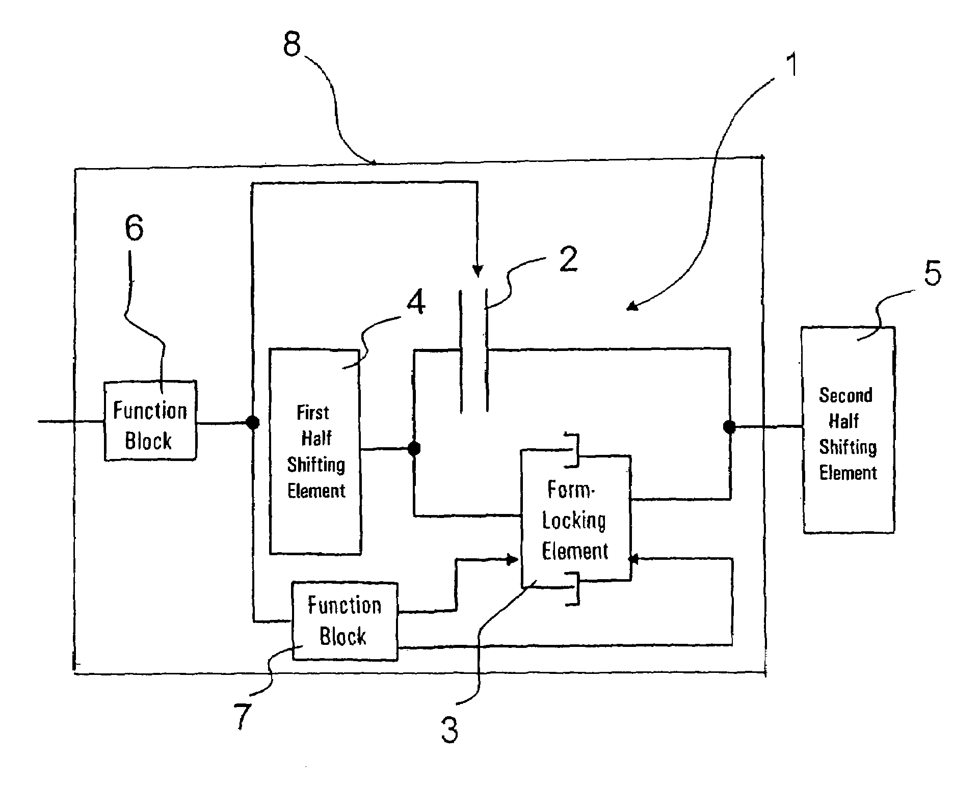
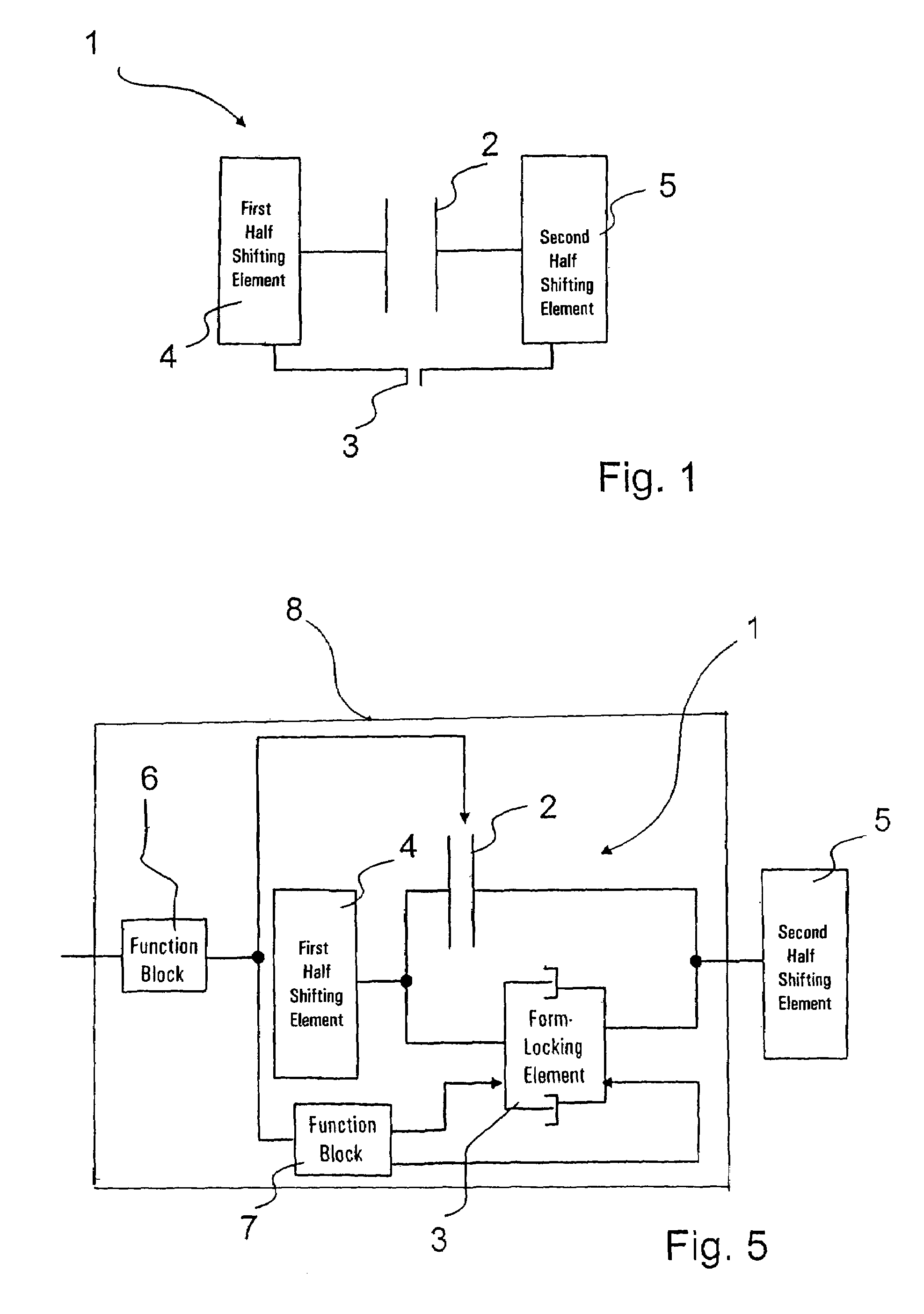
[0021]In FIG. 1 is schematically shown a shifting component 1 of a stepped automatic transmission (not shown in detail) for a vehicle and which can be used to adjust one or more gear steps of the stepped automatic transmission. To that end, the shifting component is controlled and engaged or disengaged in combination with other shifting components of the stepped automatic transmission so as to bring in one power flow of different pairs of gears of the stepped automatic transmission.

[0022]The shifting component 1 is formed by one frictionally engaged element 2 and one form-locking element 3, a torque being passed in engaged state of the shifting component from a first half 4 of the shifting component to a second half 5 of the shifting component or viceversa.

[0023]The first half 4 of the shifting component and the second half 5 of the shifting component and the rotatable or non-rotatable parts of the stepped automatic transmission connected therewith are shown schematized in FIG. 1 as...


PUM


Abstract

The control of a shifting component (1) of a stepped automatic transmission is designed with one frictionally engaged element (2) and one form-locking element (3). When this shifting component (1) is engaged, a transmitting capacity of the frictionally engaged element (2) is first adjusted and when a synchronous state of the form-locking element (3) exists, the form-locking element (3) is closed. When the form-locking element (3) is closed, a transmitting capacity of the frictionally engaged element (3) is reduced. In case of a demand for disengaging the shifting component (1) before opening under load, the form-locking element (3) and the transmitting capacity of the frictionally engaged element (2) is increased so that a power flow, which is conveyed via the closed form-locking element (3) of the shifting component (1), can be conveyed via the frictionally engaged element when the form-locking element (3) is open.

Description

[0001]This application claims priority from German Application Serial No. 103 04 050.1 filed Feb. 1, 2003.FIELD OF THE INVENTION[0002]The invention relates to a method and a device for control of a shifting component of a stepped automatic transmission.BACKGROUND OF THE INVENTION[0003]From the practice, stepped transmission are known which are operated either partially automated or fully automated wherein one automatic cycle of a gear change by the stepped transmission particularly results in relief of the driver. Especially in fully automated selector transmissions or stepped automatic transmissions, control operations like “uncoupling / starting” and “gear change” are carried out automatically according to established or adaptive programs. For reasons of comfort, it has been changed to carrying out gear changes without noticeable interruption of traction.[0004]Such stepped automatic transmissions, where the transition from one ratio step to another is executed without interruption o...

Claims


Application Information

Patent Timeline
Patent Type & Authority Patents(United States)
IPC IPC(8): B60W10/02F16D47/00F16H3/38F16H61/04F16H61/686F16H63/30
CPCF16H61/0437F16H63/3026F16H61/684F16H61/682F16H2061/0425F16H2306/46Y10T477/753Y10T477/78Y10T477/641Y10T74/19284F16H2306/50F16H2061/0474
Inventor DREIBHOLZ, RALFEBENHOCH, MICHAEL
Owner ZF FRIEDRICHSHAFEN AG
Why Eureka
Try Eureka