Fault indicator with auto-configuration for overhead or underground application
What is Al technical title?
Al technical title is built by PatSnap Al team. It summarizes the technical point description of the patent document.
a technology of fault indicators and overhead applications, applied in voltage/current isolation, power supply testing, instruments, etc., can solve the problems that the fault indicators configured for overhead applications may not perform correctly or adequately in underground applications
Inactive Publication Date: 2006-09-12
SCHWEITZER ENGINEERING LABORATORIES
View PDF14 Cites 56 Cited by
Summary
Abstract
Description
Claims
Application Information
AI Technical Summary
This helps you quickly interpret patents by identifying the three key elements:
Problems solved by technology
Method used
Benefits of technology
[0021]The fault indicator also automatically configures itself for overhead or underground applications. In an overhead application, an electromagnetic field exists about the monitored conductor. An electromagnetic sensor develops a voltage signal from the electromagnetic field, which is translated as a logic signal input to the microcontroller. If the microcontroller determines that the logic input represents the presence
Problems solved by technology
Otherwise, it can be expected that a fault indicator that is configured for an overhead appli
Method used
Image
Click on the blue label to locate the original text in one second.
Reading with bidirectional positioning of images and text.
Examples
Embodiment Construction
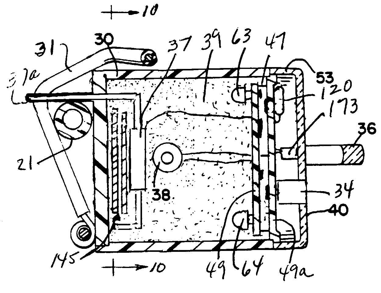
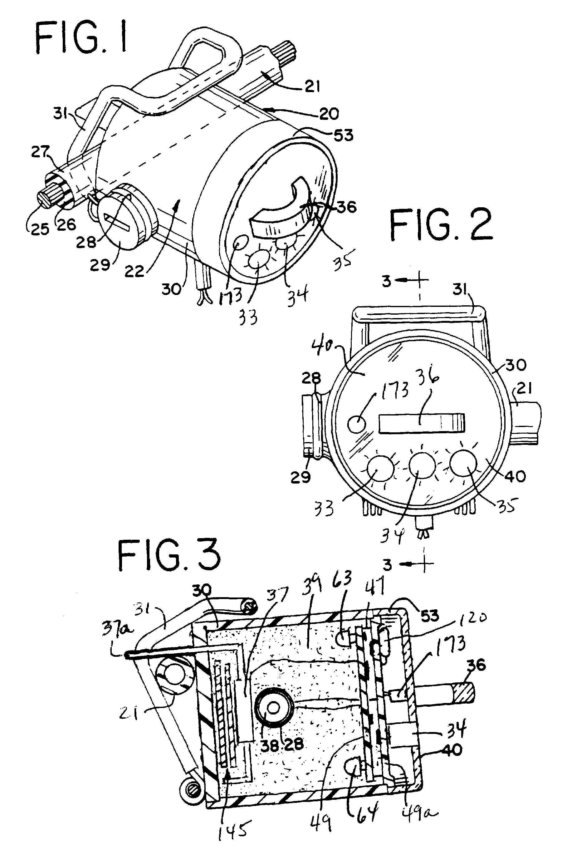
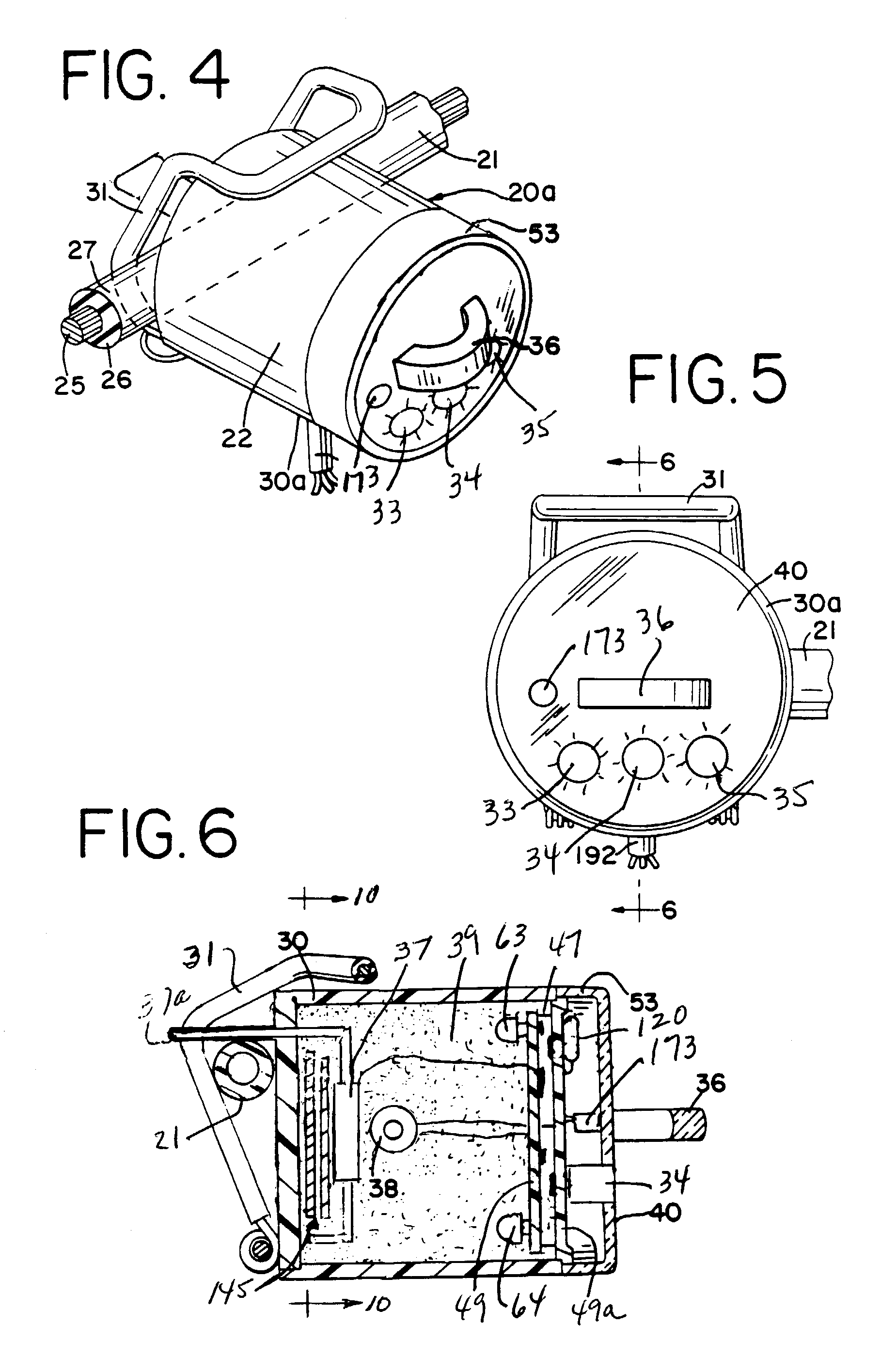
[0056]Referring to the Figures, and particularly to FIG. 1, a clamp-on timed reset fault indicator, generally designated 20, is constructed in accordance with the invention. Fault indicator 20 indicates fault currents in an electrical feeder or distribution cable, generally designated 21, and includes a circuit module, generally designated 22. Cable 21 may be part of an overhead electrical distribution system or of an underground distribution system, such as where the cable comes up from the ground at a pad-mounted transformer. In accordance with conventional practice, circuit module 22 is attached to the outer surface of the cable 21, which may include a central conductor 25, a concentric insulating layer 26 and an electrically grounded rubber outer sheath 27.
[0057]Circuit module 22 includes a housing 30 (FIG. 2) that contains electronic circuitry for sensing and responding to fault currents in cable 21. A current transformer 37 is located within housing 30 and has a pole piece 37a...
PUM
Abstract
A fault indicator for indicating the occurrence of a fault in an electrical conductor is automatically configured for an overhead application or for an underground application. The fault indicator has a housing, a battery, a display for indicating the occurrence of a fault, a current sensor for sensing the load current in a monitored conductor, and electromagnetic field sensor to sense the electromagnetic field about the conductor, and a microcontroller for determining whether a fault condition occurred, for determining the magnitude of the electromagnetic field, and for configuring the fault indicator in the overhead configuration if the electromagnetic field is above a predetermined magnitude or configuring the fault indicator for the underground mode if the field is below the predetermined magnitude. In the overhead configuration, voltage inrush restraint is enabled, the fault response time is set within a range of 1 to 50 ms, and the display is operated in bright or dims modes depending upon ambient lighting levels. In the underground configuration, inrush current restraint is enabled, the fault response time is set within a range of 1 to 24 ms, and the display is operated in only the dim mode. Related methods are also disclosed.
Description
CROSS-REFERENCE TO RELATED APPLICATIONS[0001]This patent application is a continuation-in-part patent application of the following patent applications: Microprocessor Controlled Fault Indicator with Battery Conservation Mode, Ser. No. 10 / 280,322, filed on Oct. 25, 2002 now abandoned and Ser. No. 60 / 339,412, filed on Oct. 26, 2001; Microprocessor Fault Indicator Having LED Fault Indication Circuit with Battery Conservation Mode, Ser. No. 10 / 280,219, filed on Oct. 25, 2002, now U.S. Pat. No. 6,734,662 and Ser. No. 60 / 337,631, filed on Oct. 26, 2001; Microprocessor Fault Indicator Having High Visibility LED Fault Indication, Ser. No. 10 / 280,141, filed on Oct. 25, 2002, now U.S. Pat. No. 7,053,601 and Ser. No. 60 / 339,256, filed on Oct. 26, 2001; Microprocessor Controlled Fault Indicator Having Inrush Restraint Circuit, Ser. No. 10 / 280,329, filed on Oct. 25, 2002 and Ser. No. 60 / 337,438, filed on Oct. 26, 2001; Microprocessor Controlled Directional Fault Indicator, Ser. No. 10 / 280,195, f...
Claims
Application Information
Patent Timeline
Application Date:The date an application was filed.
Publication Date:The date a patent or application was officially published.
First Publication Date:The earliest publication date of a patent with the same application number.
Issue Date:Publication date of the patent grant document.
PCT Entry Date:The Entry date of PCT National Phase.
Estimated Expiry Date:The statutory expiry date of a patent right according to the Patent Law, and it is the longest term of protection that the patent right can achieve without the termination of the patent right due to other reasons(Term extension factor has been taken into account ).
Invalid Date:Actual expiry date is based on effective date or publication date of legal transaction data of invalid patent.