
Predictive monitoring and problem identification in an information technology (IT) infrastructure

a technology of information technology infrastructure and problem identification, applied in the field of monitoring and maintaining information technology infrastructure of enterprises, can solve problems such as inability to quickly determine, inconvenient to have information about individual components or subcomponents, and large complex infrastructures

Active Publication Date: 2006-09-12
SOFTWARE AG USA
View PDF18 Cites 95 Cited by
  • Summary
  • Abstract
  • Description
  • Claims
  • Application Information

AI Technical Summary

Benefits of technology

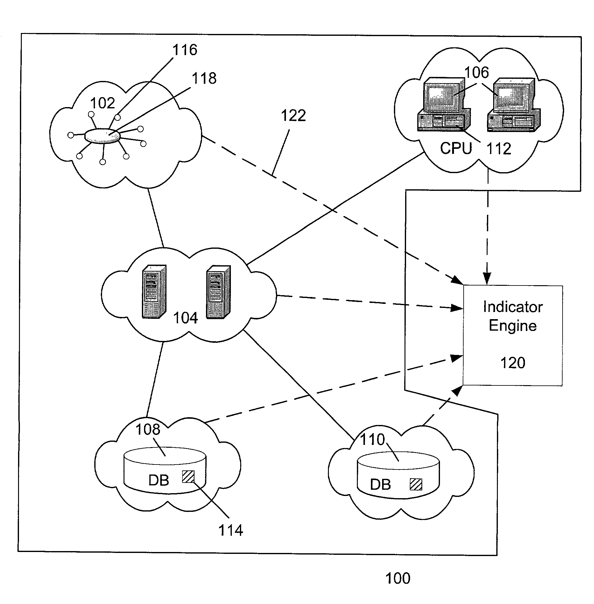
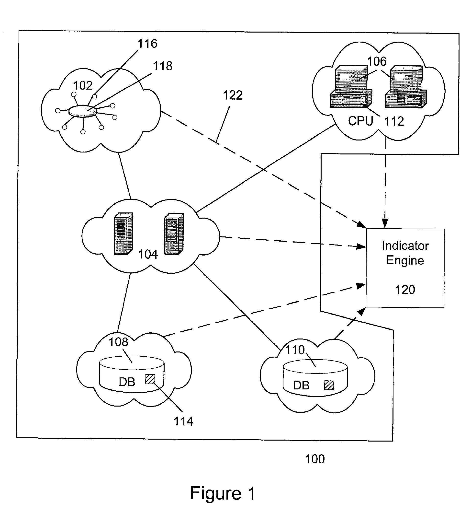
[0008]An information technology (IT) infrastructure may be monitored, and the data thus collected may be used to infer problems and predict future conditions. In one embodiment, the present invention may include receiving a plurality of component metrics, each component metric related to a corresponding component of an (IT) infrastructure of an enterprise, each component being associated with one or more gross-level rules, and generating an indicator set

Problems solved by technology

However, some enterprises have IT infrastructures so large and complex that merely having information about individual components or subcomponents may not be very helpful.
However, if a server failure combination does cause a problem so that the enterprise's website stops functioning properly, it may not be quickly determined which server or servers of the failed servers are the critical servers causing the problem.
Furthermore, prior art monitors are incapable of predicting when problems or out-of-compliance conditions, i.e. performance irregularities may occur.
Thus, IT technicians must wait until the IT infrastructure fails to function according to specification, and then they must find the cause of the failure without assistance from the monitors, other than the raw data they provide.

Method used


Image

  • Predictive monitoring and problem identification in an information technology (IT) infrastructure
  • Predictive monitoring and problem identification in an information technology (IT) infrastructure
  • Predictive monitoring and problem identification in an information technology (IT) infrastructure

Examples


Embodiment Construction

[0017]IT Infrastructure Monitoring

[0018]Embodiments of the present invention combine measurements from numerous monitors. These monitors collect data from a number of components and subcomponents of an enterprise's IT infrastructure, and provide the data regarding each of the components. Using the combined measurements, historical values of the monitors, and statistical analysis, embodiments of the present invention can predict that the IT infrastructure will not perform up to specification in the future. If the IT infrastructure is already not performing up to specification, embodiments of the present invention can suggest possible problems causing the out-of-compliance condition, and may even suggest solutions to those problems. This may be accomplished by using combined measurements and statistical analysis in a process herein referred to as “fingerprinting.” As used in this description, a fingerprint is synonymous with the term “indicator set,” a more general if somewhat less co...


PUM


Abstract

An information technology (IT) infrastructure may be monitored, and the data thus collected may be used to infer problems and predict future conditions. In one embodiment, the present invention may include receiving a plurality of component metrics, each component metric related to a corresponding component of an (IT) infrastructure of an enterprise, each component being associated with one or more gross-level rules, and generating an indicator set by comparing each received component metric to relevant historical values of the component metric. In one embodiment, the present invention may also include determining that a gross-level rule is out of compliance, comparing the indicator set to one or more historical indicator sets to determine whether the indicator set resembles any of the one or more historical indicator sets, and performing an appropriate action based on the result of the comparison.

Description

CROSS REFERENCE TO RELATED APPLICATIONS[0001]This application claims the benefit of U.S. Provisional Application Nos. 60 / 281,991, and 60 / 282,363, filed Apr. 7, 2001 both of which are incorporated herein by reference.BACKGROUND OF THE INVENTION[0002]1. Field of the Invention[0003]The present invention applies to the field of monitoring and maintaining an enterprise's information technology infrastructure and, in particular, to predicting performance irregularities in an enterprise's information technology infrastructure, and inferring possible problems causing the irregularities.[0004]2. Description of the Related Art[0005]Modern businesses rely on information technology (IT) to assist in carrying out business tasks. An enterprise's IT infrastructure needs to consistently perform to specification to ensure the success of the business. The IT infrastructure may be used for an enterprise's communication, database management, inventory tracking, shipment records, website management, bus...

Claims


Application Information

Patent Timeline
IPC IPC(8): G06F15/177
CPCH04L41/142H04L43/0817H04L41/147H04L43/0888
Inventor WOLTERS, TIMOTHY JEROME
Owner SOFTWARE AG USA
Learn More